Manufacturing method of storage element and terminal

A technology for electric storage components and external terminals, which is applied in the direction of electrical components, final product manufacturing, battery pack components, etc., to achieve the effect of simple and cheap production and simplified structure

Active Publication Date: 2016-09-07
GS YUASA INT LTD
View PDF6 Cites 0 Cited by
  • Summary
  • Abstract
  • Description
  • Claims
  • Application Information

AI Technical Summary

Problems solved by technology

[0004] However, in the above structure, only the undeformed positive electrode through-connection part is riveted and fixed on the positive electrode fixing part.

Method used


Image

  • Manufacturing method of storage element and terminal
  • Manufacturing method of storage element and terminal
  • Manufacturing method of storage element and terminal

Examples


Embodiment Construction

[0033] Embodiments of the present invention will be described below with reference to the drawings. In the following description, terms indicating specific directions or positions (such as terms including "upper", "lower", "side", and "end") are used as needed, and these terms are only for the convenience of understanding the invention with reference to the drawings. As used, the technical scope of the present invention is not limited based on the meanings of these words. In addition, the following description is merely an illustration in nature, and is not intended to limit the present invention, its applicable products, or its uses.

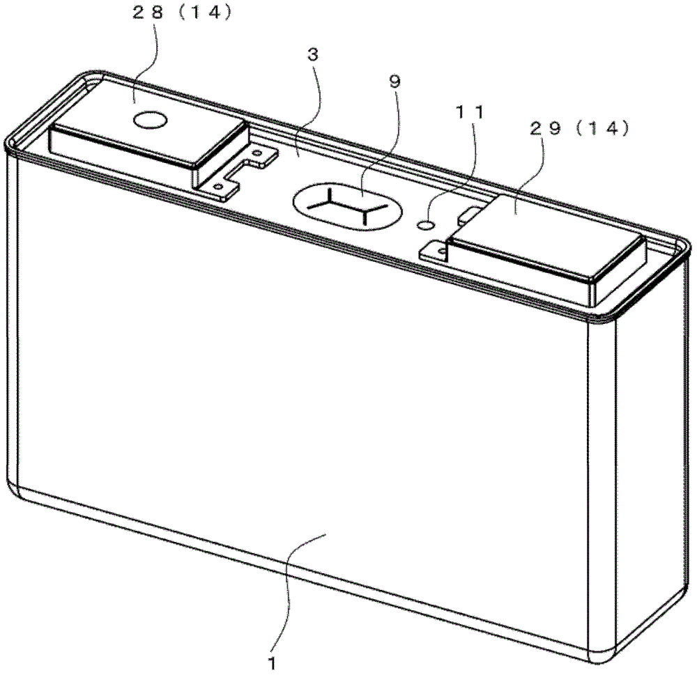
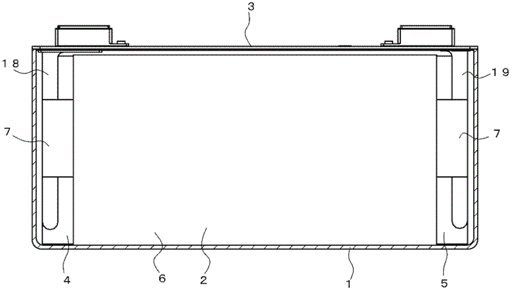
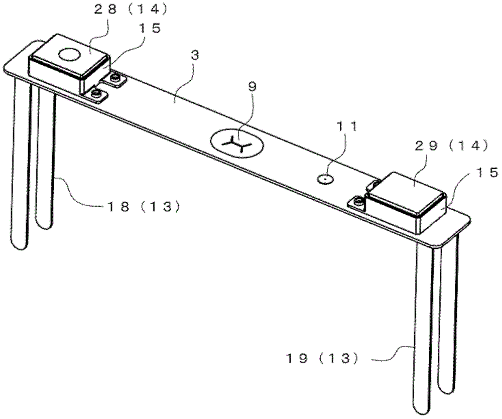
[0034] figure 1 A non-aqueous electrolyte secondary battery as an example of an electricity storage element is shown. Such as figure 2 As shown, the non-aqueous electrolyte secondary battery has a structure in which a power generating unit 2 is accommodated in a battery container 1 and sealed by a lid body 3 . Here, the exterior body is co...


PUM


Abstract

The present invention provides a method for manufacturing an electrical storage element and a terminal, which can simplify the structure of the external terminal, and can be manufactured simply and cheaply. The power storage element includes: an external terminal (14) having an exposed surface exposed from the exterior body (1, 3); body (13); and a power generating unit (2) disposed inside the exterior body (1, 3) and connected to the current collector (13). The external terminal (14) has a planar portion exposed to the outside, and a shaft portion (31) protruding from the planar portion into the exterior body and connected to the current collector (13).

Description

technical field [0001] The present invention relates to a method for manufacturing an electric storage element and a terminal. Background technique [0002] At present, in a battery as an example of an electric storage element, a structure of an external terminal is disclosed, that is, by pressing the four arms to expand into a cross shape, the undeformed positive electrode through-connection part is riveted and fixed (kashime fixed) on the The positive electrode fixing portion serves as the positive electrode overlapping portion (for example, refer to Patent Document 1). [0003] Patent Document 1: (Japanese) Unexamined Patent Publication No. 2010-33766 [0004] However, in the above structure, the undeformed positive electrode through connection portion is simply riveted and fixed on the positive electrode fixing portion. Then, the connection between the external terminal and the bus bar is performed through the positive electrode connecting portion extending from the po...

Claims


Application Information

Patent Timeline
Patent Type & Authority Patents(China)
IPC IPC(8): H01M2/30H01M2/20H01M50/571
CPCH01M50/553H01M50/55H01M50/176H01M50/562Y10T29/49204Y02E60/10H01M50/571Y02P70/50H01M50/531
Inventor 伊藤瞬
Owner GS YUASA INT LTD
Why Eureka
Try Eureka