
Photodetection mechanics test device for simulating deep rock explosion cracking

A technology of photomechanics and experimental device, applied in soil material testing, material inspection products, etc., can solve the problem that the crack propagation law in the dynamic stress field of the explosion cannot be scientifically and comprehensively analyzed and studied, and the deep rock explosion cannot be truly reproduced. Fracture law and mechanism and other issues, to achieve the effect of easy implementation and maintenance, ensuring reliability and flexibility, and convenient operation

Inactive Publication Date: 2012-07-04
CHINA UNIV OF MINING & TECH (BEIJING)
View PDF7 Cites 12 Cited by
  • Summary
  • Abstract
  • Description
  • Claims
  • Application Information

AI Technical Summary

Problems solved by technology

[0003] At present, in the physical blasting model test, most of the boundary conditions of the model are free boundary conditions, which has certain limitations for the study of the blasting theory of rock mass under high confining pressure, especially when the explosive loading device and the photomechanical experiment method ( (such as dynamic photoelasticity, dynamic caustics, etc.) in the research of blasting fracture phenomenon and mechanism, the two-dimensional plane model specimen is used, and there are no constraints around the specimen, which cannot truly reproduce the law of explosive fracture of deep rock mass, that is, rock under high ground stress. and mechanism, scientific and comprehensive analysis and research cannot be carried out on the law of crack propagation in the explosive dynamic stress field

Method used


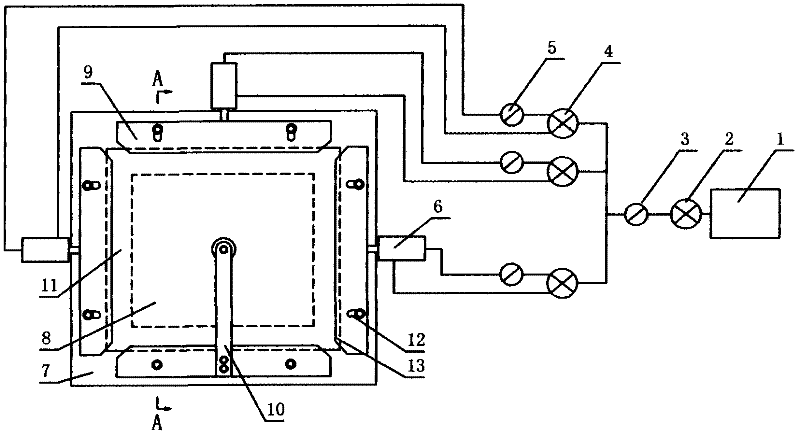
Image

  • Photodetection mechanics test device for simulating deep rock explosion cracking
  • Photodetection mechanics test device for simulating deep rock explosion cracking
  • Photodetection mechanics test device for simulating deep rock explosion cracking

Examples


Embodiment Construction

[0015] The center of the invention is: apply confining pressure to the test piece in an experimental way, simulate the ground stress in the deep rock, generate the initial static stress field in the test piece model, then pass the explosion experiment, and adopt the photomechanical method to analyze the explosion-induced stress field. Observation of the cracking process in order to study the blasting fracture phenomenon and mechanism of deep rock mass under high ground pressure, and provide scientific basis for geological excavation and blasting process.

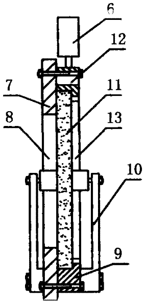
[0016] Attached below figure 1 , figure 2 The present invention is described in further detail:

[0017] An optomechanical experimental device for simulating blasting and fracturing of deep rocks. It mainly includes two parts: one part is a static loading system that can carry out stress loading on specimens along the horizontal and vertical directions; the other part is used to generate dynamic Explosive loading device 1...


PUM


Abstract

The invention discloses a photodetection mechanics test device for simulating deep rock explosion cracking, which comprises a static load system and an explosion load device, wherein the static load system can perform test sample stress load along the horizontal direction and the vertical direction, and the explosion load device is used for generating dynamic loads. The static load system comprises a vertically arranged base plate, four push plates and a pressure supplying system, wherein the four push plates are distributed on one side of the base plate along the upper direction, the lower direction, the left direction and the right direction, and the pressure supplying system respectively provides pressure for the push plates in the upper direction, the left direction and the right direction. The push plates tightly clamp the test sample during the moving process, the explosion load device exerts dynamic load on the test sample and really simulates an initial static stress field in a deep rock body and a dynamic stress field generated during the explosion process. With the combination of a photodetection mechanics test method, the photodetection mechanics test device achieves observation of phenomena of explosion cracking, cracking expansion and the like of the rock body under deep high land stress, and is a simple, convenient and practical device for scientific and accurate research.

Description

technical field [0001] The invention relates to an optical measurement and mechanics experiment device, in particular to an optical measurement and mechanics experiment device for performing physical simulation experiments on deep rock blasting and cracking. Background technique [0002] Rock mass is the product of long-term geological age. In the natural state, there are initial stresses such as self-weight stress and tectonic stress. Therefore, any dynamic load on rock mass is based on the existence of a certain static stress field. The dynamic fracture process of rock mass under the action of dynamic load is related to the static stress field. For example, in deep mines, the initial static stress field generated by high ground pressure will have a huge impact on the rock fracture phenomenon and the propagation law of explosive cracks under the blast load, and the initial static stress field effect cannot be ignored. [0003] At present, in the physical blasting model tes...

Claims


Application Information

Patent Timeline
IPC IPC(8): G01N33/24
Inventor 杨立云杨仁树许鹏郭东明
Owner CHINA UNIV OF MINING & TECH (BEIJING)
Learn More