Direct-driving oscillating gate passage

A swing type, channel technology, applied in the field of gate channels, can solve the problems of the complexity of the installation of the safety channel, inconvenient disassembly of the rotating shaft, increased maintenance difficulty, etc. The effect of reducing installation costs

Inactive Publication Date: 2012-07-04
张建新
View PDF4 Cites 4 Cited by
  • Summary
  • Abstract
  • Description
  • Claims
  • Application Information

AI Technical Summary

Problems solved by technology

This will cause the installation complexity and maintenance difficulty of the safety channel
It can be seen from the accompanying drawings that, in addition, the rotating shaft is located between the two baffles, and the rotating shaft is also used as the middle support shaft of the door base frame, which correspondingly leads to inconvenient disassembly of the rotating shaft during maintenance and increases the use process. maintenance difficulty in

Method used


Image

  • Direct-driving oscillating gate passage
  • Direct-driving oscillating gate passage
  • Direct-driving oscillating gate passage

Examples


Embodiment Construction

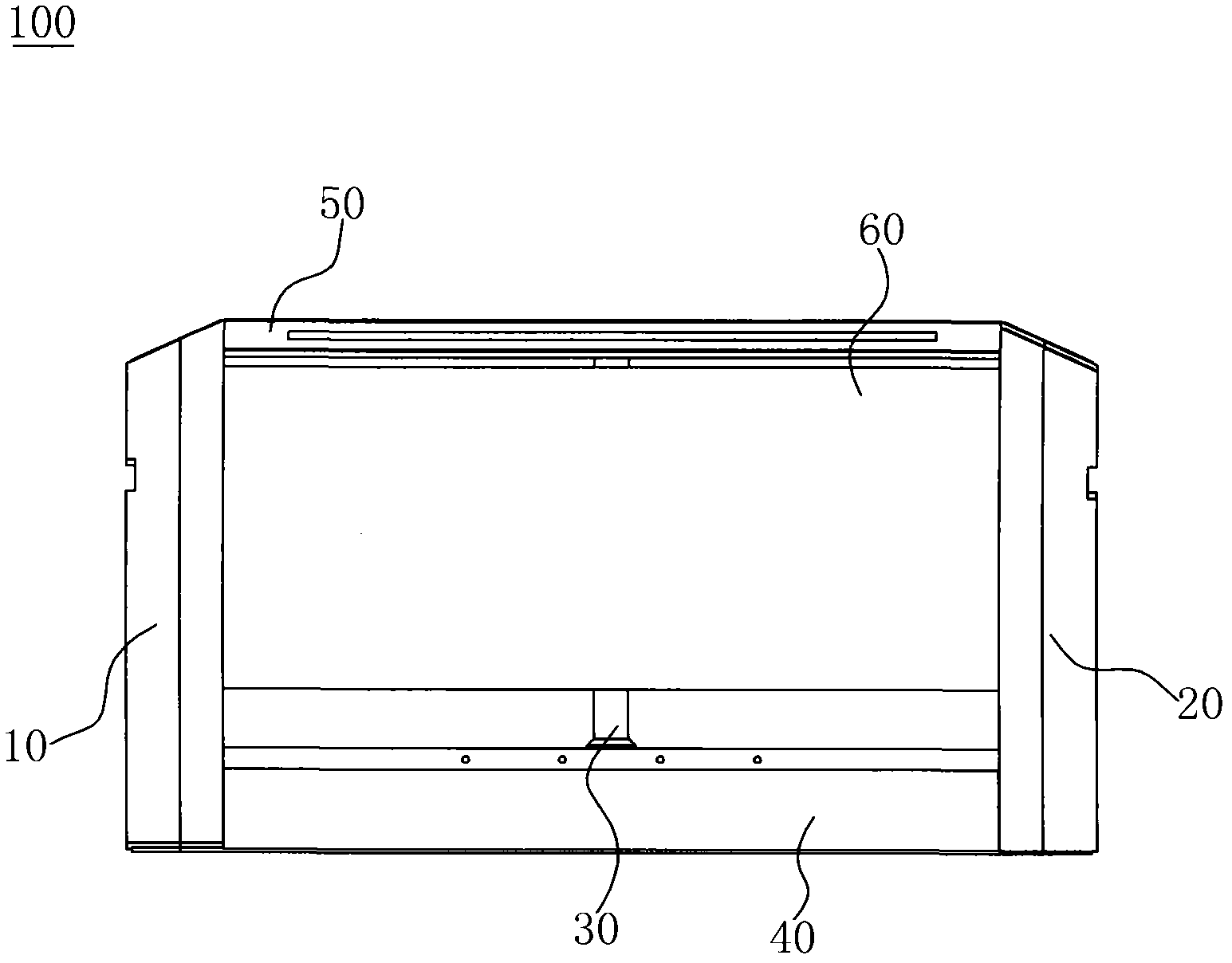
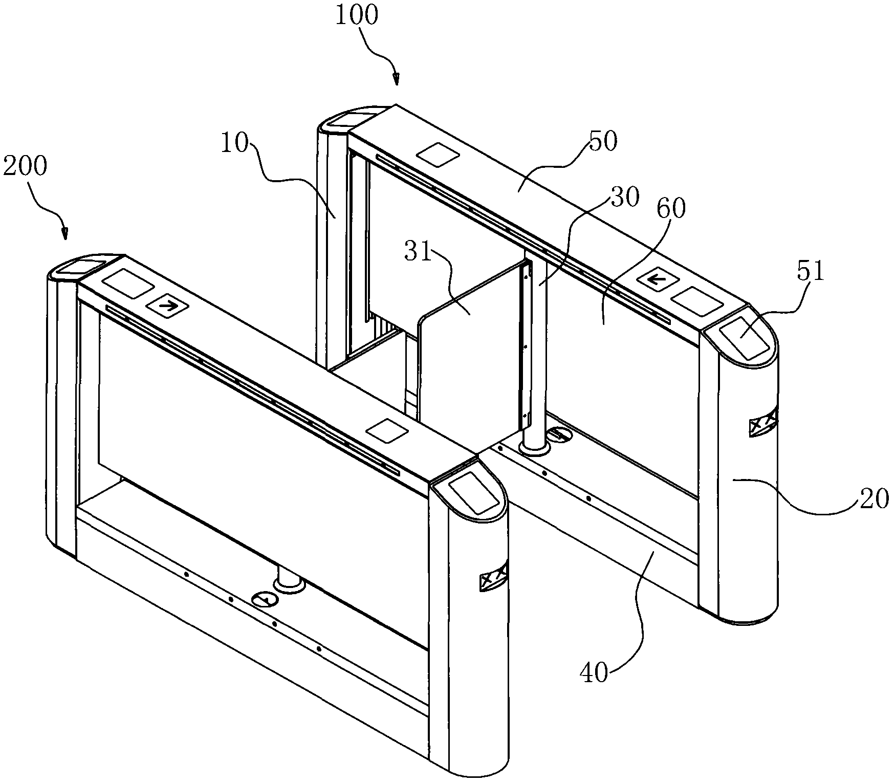
[0017] like figure 1 and figure 2 As shown, the direct-drive swing gate channel is composed of two sets of channel bases 100 and 200. The two sets of channel bases are arranged side by side and facing each other on both sides of the channel. The two channel bases are structurally symmetrical bases. The channel base 100 has a support frame body, which includes front and rear columns 10 and 20, and a control installation box 40 at the bottom of the support frame body, and the control installation box 40 is located between the front and rear columns. The control installation box is a cuboid structure arranged horizontally, in which communication and control components are arranged, and a baffle 60 is assembled in the support frame, and the two ends of the baffle 60 are fixedly arranged on the front and rear columns. The upper end surface of the control installation box is provided with a driving column 30 of the access door, and the driving column 30 is located on one side of t...


PUM


Abstract

A direct-driving oscillating gate passage comprises a passage base on the lateral part of the passage, and is characterized in that the passage base comprises a support frame body, wherein a control mounting box is arranged at the bottom of the support frame body; a driving pillar for a passage door is arranged on the control mounting box; the passage door is fixed on one side wall of the driving pillar; and a driving motor is arranged in the driving pillar, and is directly connected with and used for driving the passage door. The direct-driving oscillating gate passage has the advantages that the structural design is reasonable; the service life is long; and as the control mounting box is arranged at the bottom of the support frame body, and control components and the like of the gate passage are mounted into the control mounting box, the mounting firmness of the control components is effectively guaranteed, the service life of the direct-driving oscillating gate passage is correspondingly prolonged, and the convenience in the maintenance of the direct-driving oscillating gate passage is correspondingly improved.

Description

technical field [0001] The invention belongs to gate channel technology for controlling the entry and exit of pedestrians, in particular to a direct-drive swing gate channel with simple assembly and convenient maintenance. Background technique [0002] Existing gate passages for identification are widely used in various security checks, ticket checking and identity verification places. In the prior art, this type of gate channel is realized by using a channel base fixed to the ground, and a drive assembly for driving the opening and closing of the channel door is fixedly arranged on the channel base. The Chinese patent ZL201020138007.7 published by the applicant of this case on January 12, 2011 discloses a swing-type safety passage, which includes a door base frame, and a drive motor is arranged in the door base frame, and the drive motor is connected to a rotating shaft by driving. A swing wing is installed on one side of the rotating shaft, and the swinging wing is driven...

Claims


Application Information

Patent Timeline
Patent Type & Authority Applications(China)
IPC IPC(8): E01F13/04
Inventor 张建新
Owner 张建新
Why Eureka
Try Eureka