Automatic deslagging multi-cycle anaerobic reactor

An anaerobic reactor and automatic slag removal technology, which is applied in anaerobic digestion treatment, waste fuel, etc., can solve the problems of low wastewater treatment efficiency, gas pollution in the external area, lack of cooperation with large flow circulation devices, etc., and achieve cycle strength improvement , The effect of improving processing efficiency

Inactive Publication Date: 2012-07-04
WUXI XINDU ENVIRONMENTAL PROTECTION EQUIP
View PDF5 Cites 2 Cited by
  • Summary
  • Abstract
  • Description
  • Claims
  • Application Information

AI Technical Summary

Problems solved by technology

[0004] 1) The gas, water and mud three-phase separator installed near the liquid surface covers the foam and scum generated inside the anaerobic reactor, and cannot be cleaned manually during the operation of the equipment
These foams and scum accumulate under the three-phase separator for a long time, and gradually form blocks, which block the exhaust pipe and gas collection area, greatly reducing the treatment efficiency of the anaerobic reactor until failure occurs
In order to clean the scum in the lower part of the three-phase separator, the equipment can only be stopped and manually cleaned through large-scale maintenance projects
[0005] 2) Most of the biogas generated during the operation of the anaerobic reactor enters the gas-water separator directly through the pipeline, which is inconvenient for personnel to observe the status of the biogas:
[0006] 3) The wastewater in the upper sedimentation area of ​​the three-phase separator will still produce a certain amount of biogas, which will directly enter the air and cause gas pollution to the external area
[0007] 4) Lack of large-flow circulation device, so that the anaerobic microbial reaction in the main reaction zone of the anaerobic reactor cannot be fully carried out, and the efficiency of wastewater treatment is low

Method used


Image

  • Automatic deslagging multi-cycle anaerobic reactor
  • Automatic deslagging multi-cycle anaerobic reactor

Examples


Embodiment Construction

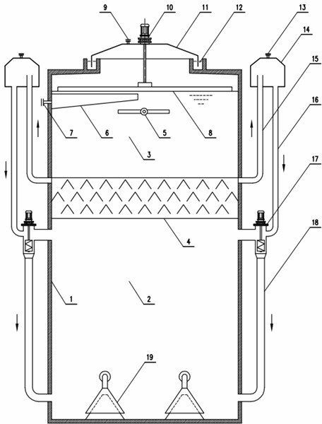
[0022] Such as figure 1 As shown, an automatic slag removal multi-cycle anaerobic reactor of the present invention mainly includes an anaerobic reactor main body 1, which may be cylindrical or rectangular in shape. In the middle of the inner cavity of the main body 1 of the anaerobic reactor, a multi-layer triangular mud separator 4 is arranged, and the multi-layer triangular mud separator 4 is arranged at 1 / 2 to 2 / 3 of the anaerobic reactor main body 1 from the bottom. The inner cavity is divided into an upper sedimentation separation zone 3 and a lower high-efficiency reaction zone 2 by the triangular mud separator 4. A water distribution device 19 is installed in the high-efficiency reaction zone 2 near the bottom of the main body of the anaerobic reactor; and the sedimentation separation zone 3 is provided Water collection device 6.

[0023] The top of the main body 1 of the anaerobic reactor is provided with a detachable gas collecting hood 11, and a water sealing groove 12...


PUM


Abstract

The invention discloses an automatic deslagging multi-cycle anaerobic reactor which can be used for effectively solving the problems of residue collection and gas-liquid separation inside a reactor. The automatic deslagging multi-cycle anaerobic reactor comprises an anaerobic reactor main body, wherein multiple layers of triangular mud separating devices are arranged inside the inner cavity of the anaerobic reactor main body, the triangular mud separating devices divide the inner cavity into a precipitation separation region at the upper part and a high-efficiency reaction region at the lower part, and a water distribution device is arranged at the part, close to the bottom of the anaerobic reactor main body, of the high-efficiency reaction region; a water collection device is arranged in the precipitation separation region, a motor is arranged at the top of the anaerobic reactor main body, the rotating shaft of the motor is inserted into the precipitation separation region and a slag scraper is arranged at the end part of the precipitation separation region, the slag scraper is horizontally arranged at a liquid level position of the precipitation separation region, a slag collection slot is arranged on the inner wall surface of the anaerobic reactor main body and is corresponding to the slag scarper, and a slag outlet is arranged at the side face of the slag collection slot.

Description

[0001] Technical field [0002] The invention relates to a sewage treatment equipment, in particular to an automatic slag removing multi-circulation anaerobic reactor, which is suitable for treating high-concentration waste water, and treating waste water that is prone to foam, scum, or high suspended matter concentration , Has stronger adaptability and processing effect. Background technique [0003] At present, a common wastewater treatment anaerobic reactor is equipped with a gas, water, and mud three-phase separator at the upper part of the reactor body near the liquid level to collect and separate gas in the water. This type of anaerobic reactor has the following definite traps: [0004] 1) The gas, water, and mud three-phase separator set close to the liquid level covers the foam and scum generated inside the anaerobic reactor, and cannot be manually cleaned during the operation of the equipment. These foams and scum are accumulated under the three-phase separator for a long...

Claims


Application Information

Patent Timeline
Patent Type & Authority Applications(China)
IPC IPC(8): C02F3/28
CPCY02E50/30
Inventor 邱小燕华素兰解建平
Owner WUXI XINDU ENVIRONMENTAL PROTECTION EQUIP
Why Eureka
Try Eureka