Device for ventilating and aerating a fuel tank

A fuel tank, connected technology, applied in the field of ventilation and ventilation devices, can solve problems such as destruction, freezing, valve damage, etc.

Inactive Publication Date: 2012-07-04
AUDI AG
View PDF7 Cites 0 Cited by
  • Summary
  • Abstract
  • Description
  • Claims
  • Application Information

AI Technical Summary

Problems solved by technology

When the condensate contains moisture, at low ambient temperatures this can lead to freezing and, especially in the case of fuel tank shut-off valves, damage or destruction of the valve

Method used


Image

  • Device for ventilating and aerating a fuel tank
  • Device for ventilating and aerating a fuel tank
  • Device for ventilating and aerating a fuel tank

Examples


Embodiment Construction

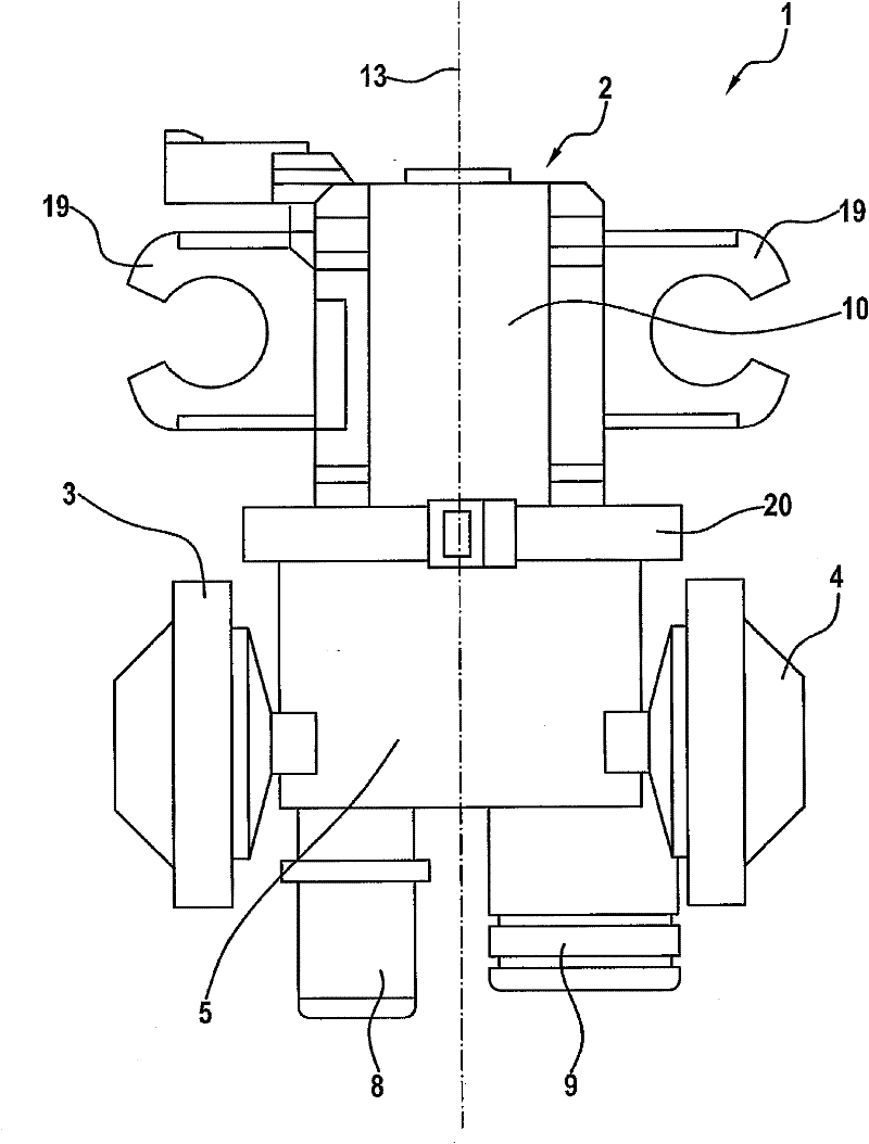
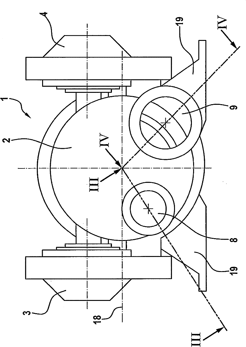
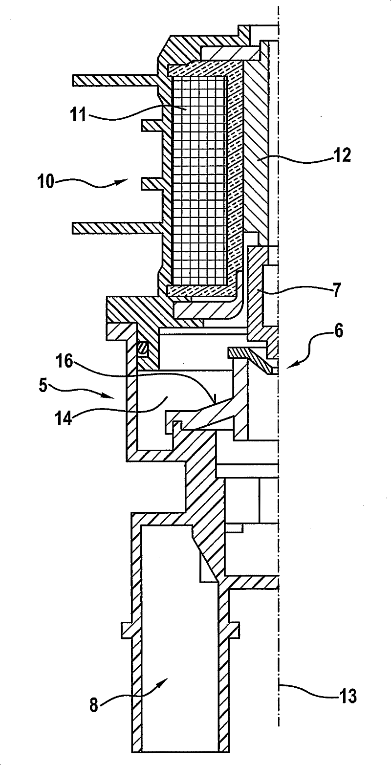
[0069] Figures 1 to 4 The valve unit 1 shown in is used for ventilation and ventilation of a fuel tank (not shown) and is intended to be installed between the fuel tank and an activated carbon filter (not shown) Prevent volatile hydrocarbons from being released into the atmosphere or environment during ventilation and ventilation.

[0070] The valve unit 1 basically consists of a tank shut-off valve 2 and two tank pressure regulating valves 3 , 4 spaced apart from each other and arranged on opposite (both) sides of the tank shut-off valve 2 .

[0071] The fuel tank shut-off valve 2 is a solenoid valve comprising two parts connected to each other in a rotatable manner, namely a valve part 5 and a valve actuating part 10, said valve part 5 having a valve seat 6 movable relative to the valve seat 6 valve element 7 and two connections 8, 9, namely a fuel tank connection 8 that can be connected to a fuel tank and a filter connection 9 that can be connected to an activated carbon ...


PUM


Abstract

A device for ventilating and aerating a fuel tank includes a tank shut-off valve and two tank pressure control valves. One of the tank pressure control valves opens in response to an overpressure in the fuel tank and the other one of the tank pressure control valves closes in response to a negative pressure in the fuel tank. A valve unit which is formed from one or multiple of the valves is mountable vertically or horizontally and has a fuel connection which communicates with the fuel tank and a filter connection which communicates with an activated carbon filter. The two connections are generally oriented parallel and point downwards in vertical mounting position of the valve unit and in sideward direction(s) in horizontal mounting position of the valve unit and are arranged at or near the bottom side of the valve unit.

Description

technical field [0001] The invention relates to a device for ventilation and ventilation of fuel tanks according to the preamble of claim 1 . Background technique [0002] In motor vehicles, a device of the type mentioned at the outset is provided between the fuel tank and an activated carbon filter which is intended to prevent the undesired escape of volatile hydrocarbons from the fuel tank into the environment of the motor vehicle . The fuel tank shut-off valve is a controllable valve, such as a solenoid valve, which is normally closed and which is open during refueling of the fuel tank to direct the gas mixture expelled from the fuel tank through the activated carbon filter, and absorbs the hydrocarbons (HC) contained in the gas mixture, so only purified air reaches the environment. The two tank pressure regulator valves are the overpressure valve and the low / negative pressure valve, which are also normally closed. In the event of a predetermined overpressure inside th...

Claims


Application Information

Patent Timeline
Patent Type & Authority Applications(China)
IPC IPC(8): B60K15/035
CPCF02M25/0836B60K2015/03302B60K15/03519B60K2015/03514B60K2015/03276B60K2015/03566Y10T137/7771Y10T137/7779Y10T137/778
Inventor H・哈根
Owner AUDI AG
Why Eureka
Try Eureka