Eureka AIR delivers breakthrough ideas for toughest innovation challenges, trusted by R&D personnel around the world.

Scarf rope twisting and knot tying machine and rope twisting and knot tying method

A knotter and scarf technology, which is applied to scarves, scarves, head scarves and other directions, can solve the problems of a large number of labors, ununified and time-consuming rope knotting work, saving production and processing time, shortening product delivery, The effect of ideal appearance

Inactive Publication Date: 2012-07-04
沈文标
View PDF5 Cites 6 Cited by
  • Summary
  • Abstract
  • Description
  • Claims
  • Application Information

AI Technical Summary

Problems solved by technology

[0003] The problem with the current method of twisting and knotting scarves is that no matter what method is used to weave the scarf during production, it will encounter certain difficulties in making tassels at the end. However, this method is very time-consuming and requires a lot of labor, and because the manual rope knotting work cannot be completed uniformly and simultaneously, the tassels produced are uneven in thickness, and the appearance effect is not fine. The knuckles can't guarantee the same position, so that the quality of the whole scarf is greatly reduced. At present, there are some machines on the market that can twist the scarf. Combined, the effect is not ideal

Method used


Image

  • Scarf rope twisting and knot tying machine and rope twisting and knot tying method
  • Scarf rope twisting and knot tying machine and rope twisting and knot tying method
  • Scarf rope twisting and knot tying machine and rope twisting and knot tying method

Examples


Embodiment 1

[0017] Embodiment 1: with reference to attached Figure 1-8 , a scarf rubbing rope knotting machine, which includes a frame 1, a positioning device, a rope rubbing device and a knotting machine, the frame 1 includes a bottom beam 2 and a middle beam, and a hook knife runs through the middle of the bottom beam 2 Groove 3, lifting arrangement type hook knife 4 is arranged in the hook knife groove 3 in the middle of the bottom beam 2, the lower washboard 5 is arranged on the bottom beam 2 of the frame 1, and the slideway 6 is arranged on the left and right sides of the bottom beam 2, and the The knotting machine is installed on the middle beam of the frame 1. The positioning device includes upper and lower pressure plates 7, 8 and slideways 6. The lower pressure plate 8 is arranged on the slideways 6 on both sides of the bottom beam, and is parallel to the bottom beam 2. The pressure plate 7 is arranged above the corresponding lower pressure plate through the lifting rod 9. The s...

Embodiment 2

[0018] Embodiment 2: with reference to attached figure 1 , 4And 5, a scarf rubbing rope knotting machine, the knotting machine includes a knotting head 16, a reel 17 and a crotch 18, the knotting head 16 is columnar, and is evenly arranged on the lifting beam 19, the upper and lower rubber The presser feet 20, 21 are arranged on the slideways 6 on both sides of the bottom beam 2. The upper and lower rubber presser feet 20, 21 can not only be used for positioning the rope-shaped tassels, but also because the rubber presser feet have certain elasticity, it is convenient to press the rope-shaped tassels. Twitching, the winding head 22 is fixed on the bottom of the knotting head 16, and the end side of the winding head 22 is provided with a protrusion 23, and the protrusion 23 can prevent the rope-shaped tassel wound on the winding head 22 from slipping, so that the knotting is successful. Efficiency improves greatly, and reel 17 is installed on the side of knotting head 16, and ...

Embodiment 3

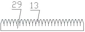
[0019] Embodiment 3: On the basis of Embodiments 1 and 2, when rubbing the rope, place the two ends of the scarf on the lower pressing plate 8 of the frame 1, and manipulate the controller 28 to lower the upper pressing plate 7 to be in close contact with the corresponding lower pressing plate 8. Thereby the scarf is fixed and the reserved weft yarn is placed between the pressing plates on both sides of the frame, and then the lower pressing plate 8 is pushed back and forth to slide along the slideways 6 on both sides of the frame 1 to make the weft yarn bounce back and forth put, so that the weft yarn is tightened between the pressure plates on both sides of the frame. After the weft yarn of the scarf is tightened, the small split plate is instructed to rise, and the split teeth of the small split plate will tighten the weft yarn Divide the thread into small strands of equal parts, and then operate the lifting and translation device 14 to lower the upper washboard 12 until it ...


PUM


Abstract

The invention relates to a scarf rope twisting and knot tying machine and a rope twisting and knot tying method, wherein the scarf rope twisting and knot tying machine can automatically twist weft yarns reserved in a scarf into even and unified rope-shaped tassels in a strand-split mode, cut off the yarns and tie off. The scarf rope twisting and knot tying machine comprises a machine frame, a positioning device, a rope twisting device and a knot tying machine. The machine frame comprises a bottom beam and a middle beam, a bush-hook groove vertically penetrates through the middle of the bottom beam, lifting arrangement type bush-hooks are arranged in the bush-hook groove in the middle of the bottom beam, a lower twisting plate is arranged on the bottom beam of the machine frame, slide ways are arranged on the left side and the right side of the bottom beam, and the knot tying machine is installed in a middle cross beam of the machine frame. The scarf rope twisting and knot tying machine and the rope twisting and knot tying method have the advantages of 1 being capable of automatically fishing work that the weft yarns reserved in the scarf are twisted into ropes and tied off, greatly saving producing and processing time and simultaneously reducing work amount of workers, and 2 very uniformly performing rope twisting and knot tying work and enabling produced tassels to be even in thickness, delicate in appearance and perfect and ideal in effect.

Description

technical field [0001] The invention relates to a method that can automatically divide and twist the weft yarns reserved for scarves into uniform and uniform rope-like tassels and cut and tie them, which not only saves a lot of time and workload, speeds up the production progress, but also makes the products The utility model relates to a scarf twisting rope knotting machine and a twisting rope knotting method with finer and more perfect appearance effects, belonging to the field of textile machinery manufacturing. Background technique [0002] Scarves are an indispensable fabric in people's daily life. There are three processing methods: weaving, knitting and hand-knitting. During the manufacturing process, in order to make the scarf more beautiful, part of the weft yarn is usually reserved at the end of the scarf. thread, and this part of the weft yarn is made into a rope tassel and then knotted. [0003] The problem with the current method of twisting and knotting scarve...

Claims


Application Information

Patent Timeline
Patent Type & Authority Applications(China)
IPC IPC(8): A41D23/00
Inventor 沈文标
Owner 沈文标
Why Eureka
Eureka Blog
Learn More