Adjustable clamp for testing battery and mounting method thereof

A battery and battery technology to be tested, applied in the direction of measuring electricity, measuring devices, measuring electrical variables, etc., can solve the problems of lack of detection ability, limited adjustment range, easy to loose, etc., to improve rigidity, easy operation, and easy installation. effect of operation

Active Publication Date: 2014-12-17
DONGGUAN LARGE ELECTRONICS CO LTD
View PDF5 Cites 0 Cited by
  • Summary
  • Abstract
  • Description
  • Claims
  • Application Information

AI Technical Summary

Problems solved by technology

But it also has some problems, such as: it only has one stall, and it is positioned by pressing the battery under test, so it is only suitable for clamping square batteries. For round or irregular shaped batteries, the installation is fixed It is prone to loosening; the setting position of the test pin is relatively fixed, and the adjustment range is limited (only simple height adjustment is possible). For batteries whose electrode positions are far apart, they do not have the ability to detect and have poor versatility.

Method used


Image

  • Adjustable clamp for testing battery and mounting method thereof
  • Adjustable clamp for testing battery and mounting method thereof
  • Adjustable clamp for testing battery and mounting method thereof

Examples


Embodiment 1

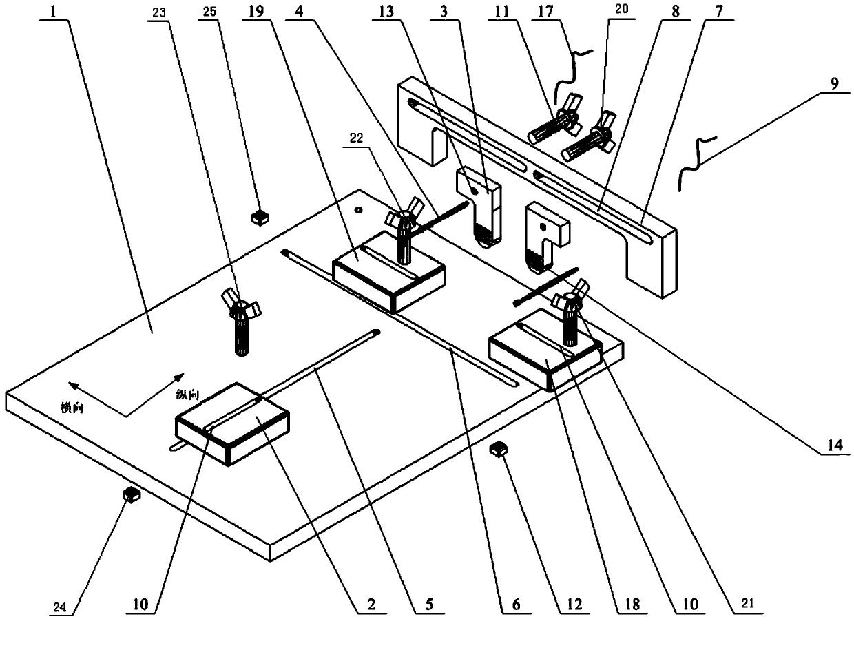
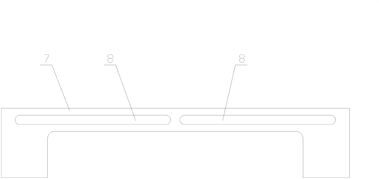
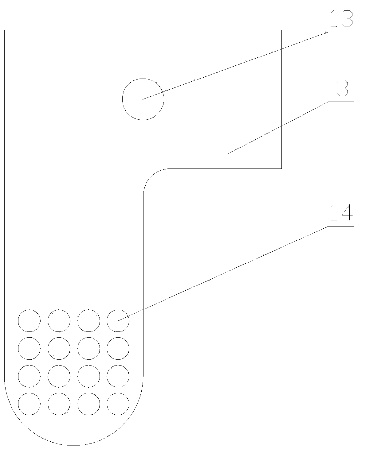
[0045] Such as Figure 4 As shown, the battery 15 to be tested has an irregular shape. First, the battery 15 to be tested is placed on the base 1, and the electrodes 16 on it are placed in the direction of the main bracket 7, and then the third threaded knob 21 is rotated to loosen the arrangement. On the guide groove b6, the second clamping block 18 and the third clamping block 19, in the guide groove b6, adjust the position of the second clamping block 18 and the third clamping block 19, and pass the second clamping block 18 Adjust the relative position of the second clamping block 18 and the third clamping block 19 with the guide groove d10 on the third clamping block 19, and rotate and adjust the angle of the second clamping block 18 and the third clamping block 19, so that Fit the battery 15 to be tested, and after adjustment, fasten the second clamping block 18 and the third clamping block 19 on the guide groove b6 through the third threaded knob 21 and the fourth thread...

Embodiment 2

[0047] Such as Figure 5 As shown, the battery to be tested 15 has a rectangular structure. First, the battery to be tested 15 is placed on the base 1, and the electrode 16 on it is placed towards the direction of the main bracket 7, and then the third threaded knob 21 and the fourth threaded knob are passed. 22 Rotate and loosen the second clamping block 18 and the third clamping block 19 arranged on the guide groove b6, adjust the position of the second clamping block 18 and the third clamping block 19 in the guide groove b6, and pass the first The guide groove d10 on the second clamping block 18 and the third clamping block 19 adjusts the relative position of the second clamping block 18 and the third clamping block 19, and rotates and adjusts the second clamping block 18 and the third clamping block 19, so as to fit the battery under test 15, after adjustment, the second clamping block 18 and the third clamping block 19 are fastened on the guide groove b6 through the third...


PUM


Abstract

The invention discloses an adjustable clamp for testing a battery and a mounting method thereof. The adjustable clamp comprises a base, clamping devices, a needle frame and a test needle, wherein the a guide slot a is formed in the base longitudinally, a guide slot b is formed in the base transversely, the clamping devices are respectively arranged on the guide slot a and the guide slot b through fixing devices, a main support is arranged on the base at one side of the guide slot b which is arranged transversely, a guide slot c is formed in the main support along a transverse direction, the needle frame is arranged on the guide slot c through the fixing device, a needle pass hole is formed in the needle frame, one end of the test needle is placed in the needle pass hole, and the other end of the test needle is connected with a test device through a electric wire. According to the invention, the position of the test needle can be adjusted correspondingly while batteries to be tested, of various shapes, can be clamped stably, so that the batteries with different electrode positions and different external structures can be detected, and the adjustable clamp is simple in structure and convenient to operate.

Description

technical field [0001] The invention relates to a fixture for testing batteries, in particular to an adjustable fixture for testing batteries and an installation method thereof. Background technique [0002] In recent years, with the rapid development of science and technology, more and more portable electronic products have appeared in our daily life, such as mobile phones, notebook computers, PDAs, etc., and batteries have also been increasingly used in these portable electronic products . As the functions of portable electronic products are gradually improved and their uses are diversified, they are used more and more frequently in daily life, so higher requirements are put forward for the quality of the batteries used to meet the needs of use. [0003] At present, the finished battery needs to be strictly inspected when it is shipped, and the two very important inspection items are voltage and internal resistance. When checking the battery voltage and internal resistan...

Claims


Application Information

Patent Timeline
Patent Type & Authority Patents(China)
IPC IPC(8): G01R1/04G01R31/36
Inventor 蒋志刚
Owner DONGGUAN LARGE ELECTRONICS CO LTD
Why Eureka
Try Eureka