Eureka AIR delivers breakthrough ideas for toughest innovation challenges, trusted by R&D personnel around the world.

Movable dehumidifier and control method thereof

A control method and dehumidifier technology, applied in heating and ventilation control systems, heating methods, household heating and other directions, can solve problems such as inconvenience and waste of electricity, and achieve the effect of reducing power consumption and facilitating operation and use.

Active Publication Date: 2012-06-27
AUX AIR CONDITIONING LTD BY SHARE LTD
View PDF7 Cites 19 Cited by
  • Summary
  • Abstract
  • Description
  • Claims
  • Application Information

AI Technical Summary

Problems solved by technology

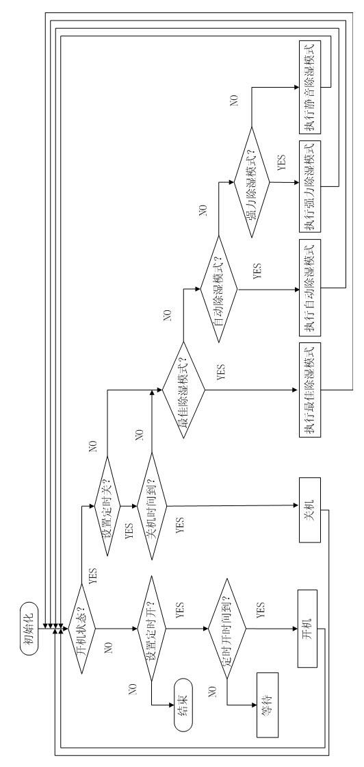
When using the timer switch method, if the room humidity meets the user's requirements and the set off time has not yet arrived, the compressor will still be turned on, which will waste electricity in vain.
In another situation where the timer switch is used, the indoor humidity does not meet the user's requirements, but the set shutdown time is up and the compressor is turned off, which is very inconvenient to use.

Method used


Image

  • Movable dehumidifier and control method thereof
  • Movable dehumidifier and control method thereof
  • Movable dehumidifier and control method thereof

Examples


Embodiment Construction

[0023] In order to make the technical means, creative features, goals and effects achieved by the present invention easy to understand, the present invention will be further described below in conjunction with specific illustrations.

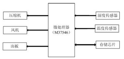
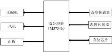
[0024] Such as figure 1 As shown, the control system of the mobile dehumidifier in this embodiment includes a microprocessor (M37546), a compressor, a fan, a panel, a temperature sensor, a humidity sensor, and a memory chip. The temperature sensor collects ambient temperature information; the humidity sensor collects ambient humidity information; the panel has a "Setting" button for the user to set the humidity information, with "automatic dehumidification", "powerful dehumidification", "quiet dehumidification", "best dehumidification" The button is for the user to select the mode information. The above information is transmitted to the microprocessor, and the microprocessor controls the operation of the compressor and the blower according to t...


PUM


Abstract

The invention relates to a movable dehumidifier. A humidity sensor and a temperature sensor are arranged on a machine case, a liquid level sensor is also arranged in a water container, a setting press button is also arranged on a panel and is used for humidity setting, and automatic dehumidification, strong force dehumidification, silence dehumidification and optimum dehumidification press buttons are adopted for mode selection. The invention also relates to a control method of the movable dehumidifier. The control of the movable dehumidifier is more intelligentized and humanized.

Description

technical field [0001] The invention relates to a mobile dehumidifier and a control method thereof, belonging to the field of household air dehumidification and environment regulation. Background technique [0002] The current mobile dehumidifier is mainly composed of a compressor, an evaporator, a fan, a water container, a casing and a microprocessor. The compressor starts, and the evaporator realizes the cooling function; the air is drawn into the casing by the fan, and the water vapor in it encounters the evaporator with a lower temperature and condenses into water droplets and collects into the water saver, and the rest becomes a dry gas discharge machine shell. The mobile dehumidifier reciprocates in this way, reducing the indoor humidity. [0003] Compared with conventional dehumidifiers, the mobile dehumidifier saves the condenser, saves costs, and is equipped with casters to facilitate the user's movement. [0004] Existing mobile dehumidifiers generally have two ...

Claims


Application Information

Patent Timeline
Patent Type & Authority Applications(China)
IPC IPC(8): F24F11/02
Inventor 陈红龚卫强
Owner AUX AIR CONDITIONING LTD BY SHARE LTD
Why Eureka
Eureka Blog
Learn More