
Ocean current energy power generation device

A power generation device and ocean current energy technology, applied in ocean energy power generation, fluid pressure actuators, hydroelectric power generation, etc., can solve the problems of inconvenient maintenance, high cost, high cost, etc., to prevent excessive rotation and high stability , low cost effect

Inactive Publication Date: 2012-06-27
NINGBO INST OF TECH ZHEJIANG UNIV ZHEJIANG
View PDF6 Cites 10 Cited by
  • Summary
  • Abstract
  • Description
  • Claims
  • Application Information

AI Technical Summary

Problems solved by technology

[0002] Ocean current power generation has always been a key technical issue of marine countries all over the world. At present, there are many types of ocean current generators, but in general, the overall structure of ocean current generators in the prior art is too complicated, especially the ocean current in the generator. Most of the energy collection units use large and expensive components, such as large blades, etc. These components are not only expensive but also inconvenient to maintain. Although some ocean current energy collection units in generators are low-cost Cost components, but its design structure is complicated, once its operation fails, it needs special engineering personnel to repair, and the maintenance is very inconvenient
At the same time, the ocean current generators in the prior art generally connect the ocean current energy harvesting unit with the generator through a simple transmission mechanism, which is greatly affected by ocean current fluctuations during operation, and the generator will run quickly when the ocean current flow is large , when the ocean current flow is small, the generator also rotates slowly, this frequency instability will cause great damage to the generator, and also reduce the reliability of the entire ocean current power generation device

Method used


Image

  • Ocean current energy power generation device
  • Ocean current energy power generation device
  • Ocean current energy power generation device

Examples


Embodiment Construction

[0021] The present invention will be described in further detail below in conjunction with the accompanying drawings.

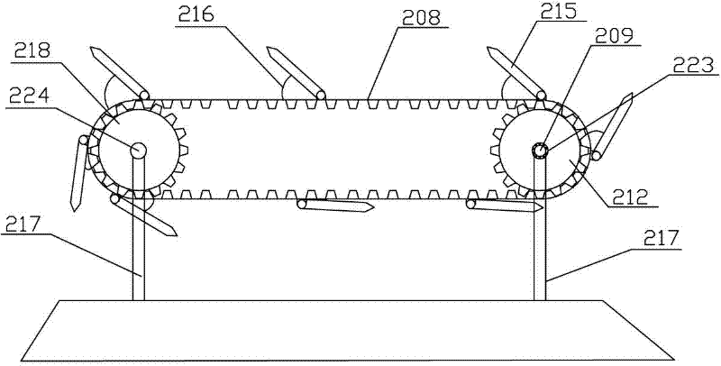
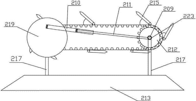
[0022] as attached figure 1 As shown, it includes a generator 201, an ocean current energy collection unit and a transmission unit; the ocean current energy collection unit is connected to the transmission unit, and the transmission unit is connected to the generator 201; A blockage part opened toward the sea current direction drives two gears to rotate synchronously; the transmission unit is a hydraulic transmission unit, which includes a hydraulic cylinder 210, an oil tank 207, an accumulator 203 and a hydraulic motor 202, and the hydraulic cylinder 210 is installed On the hydraulic cylinder base 220 that rotates synchronously and eccentrically with a gear on the ocean current energy harvesting unit, the free end of the piston rod 211 on the hydraulic cylinder 210 is in rotation with the first rotating shaft 209; the bottom end of the hydraulic cylinder 210...


PUM


Abstract

The invention relates to an ocean current energy power generation device, which comprises a power generator (201), an ocean current energy acquisition unit and a transmission unit. The ocean current energy power generation device is characterized in that the ocean current energy acquisition unit has a structure utilizing a plurality of current baffle components which open to the ocean current direction in ocean current impact to drive two gears to rotate synchronously, the transmission unit is a hydraulic transmission unit and comprises hydraulic cylinders (210), an oil tank (207), an energy accumulator (203) and a hydraulic motor (202). Affection of ocean current energy fluctuation onto the ocean current energy power generation device is low so that the ocean current energy power is more stable in running. The ocean current energy acquisition unit of the ocean current energy power generation device is simpler in structure and more convenient in maintenance.

Description

technical field [0001] The invention relates to the technical field of ocean current energy power generation, in particular to an ocean current energy power generation device. Background technique [0002] Ocean current power generation has always been a key technical issue of marine countries all over the world. At present, there are many types of ocean current generators, but in general, the overall structure of ocean current generators in the prior art is too complicated, especially the ocean current in the generator. Most of the energy collection units use large and expensive components, such as large blades, etc. These components are not only expensive but also inconvenient to maintain. Although some ocean current energy collection units in generators are low-cost Cost components, but its design structure is complicated, once its operation fails, it needs special engineering personnel to repair, and the maintenance is very inconvenient. At the same time, the ocean curr...

Claims


Application Information

Patent Timeline
Patent Type & Authority Applications(China)
IPC IPC(8): F03B13/22F03B9/00F15B15/18F15B1/02
CPCY02E10/38Y02E10/20Y02E10/30
Inventor 张智焕
Owner NINGBO INST OF TECH ZHEJIANG UNIV ZHEJIANG
Learn More