
High-temperature spiral conveyor

A screw conveyor and screw conveying shaft technology, which is applied in the field of high-temperature material conveying equipment, can solve problems such as bearing deformation, spiral inner shaft blade deformation, and blockage, and achieve good economic and social benefits, reasonable and compact design, and reduced damage. Effect

Inactive Publication Date: 2012-06-27
洛阳绿之海环保工程有限公司
View PDF3 Cites 9 Cited by
  • Summary
  • Abstract
  • Description
  • Claims
  • Application Information

AI Technical Summary

Problems solved by technology

At present, the existing screw conveyors are used to transport materials at room temperature and lower than 400°C. When conveying high-temperature materials higher than 400°C, the screw inner shaft, outer wall and blades of the screw conveyor are prone to deformation, and the bearings are lubricated. Oil evaporation will also cause deformation, clogging, jamming and damage, which will cause damage to the screw conveyor

Method used


Image

  • High-temperature spiral conveyor
  • High-temperature spiral conveyor

Examples


Embodiment Construction

[0012] The technical solution of the present invention will be described in further detail below with reference to the accompanying drawings and embodiments.

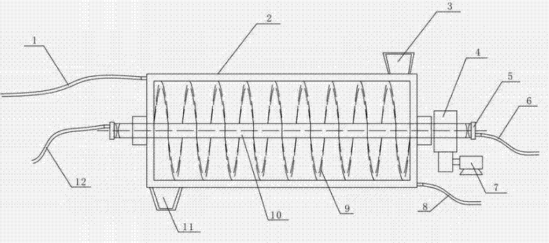
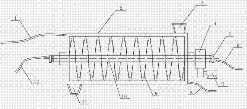
[0013] Such as figure 1 As shown, the high-temperature screw conveyor includes a motor 7, a reducer 4, a housing 2 and a screw conveying shaft 10, the screw conveying shaft is installed in the housing, the motor 7 is connected with the screw conveying shaft 10 through a reducer 4, and the screw conveying Spiral blades 9 are evenly installed on the outside of the shaft; the screw conveying shaft is a hollow shaft, and the two ends of the spiral conveying shaft 10 are respectively connected to the first water inlet pipe 6 and the first water outlet pipe 12 through the rotary joint 5; Layer structure, a cavity is provided between the inner and outer layers, the two ends of the casing are connected with a second water inlet pipe 8 and a second water outlet pipe 1, and the second water inlet pipe and the second water outlet ...


PUM


Abstract

The invention discloses a high-temperature spiral conveyor. The high-temperature spiral conveyor comprises a motor, a speed reducer, a shell and a spiral conveying shaft, wherein the spiral conveying shaft is arranged in the shell; the motor is connected with the spiral conveying shaft through the speed reducer; spiral blades are arranged on the outer side of the spiral conveying shaft uniformly; the spiral conveying shaft is a hollow shaft; two ends of the spiral conveying shaft are connected with a first water inlet pipe and a first water outlet pipe respectively through rotating joints; the shell has a double-layer structure comprising an inner layer and an outer layer; a cavity is formed between the inner layer and the outer layer; two ends of the shell are connected with a second water inlet pipe and a second water outlet pipe; and the second water inlet pipe and the second water outlet pipe are communicated with the cavity of the shell. The high-temperature spiral conveyor has a simple structure and reduces the temperature of main parts of the spiral conveyor by a spiral conveying shaft and shell double water-cooled method so as to reduce damage to the spiral conveyor and guarantee normal transportation of the materials at a high temperature of between 800 and 1,000 DEG C, and has good economic benefits and social benefits.

Description

technical field [0001] The invention belongs to the technical field of high-temperature material conveying equipment, and in particular relates to a high-temperature screw conveyor. Background technique [0002] Screw conveyors are suitable for conveying bulk materials in cement, chemical, metallurgical and other industries. At present, the existing screw conveyors are used to transport materials at room temperature and lower than 400°C. When conveying high-temperature materials higher than 400°C, the screw inner shaft, outer wall and blades of the screw conveyor are prone to deformation, and the bearings are lubricated. Oil evaporation will also cause deformation, clogging, jamming and damage, which will cause damage to the screw conveyor. Therefore, how to make the screw conveyor work normally when conveying high-temperature bulk materials has become a problem to be solved. Contents of the invention [0003] In order to solve the above problems, the object of the prese...

Claims


Application Information

Patent Timeline
Patent Type & Authority Applications(China)
IPC IPC(8): B65G33/14B65G33/24
Inventor 刘仲国李贵洲周松泉张斌
Owner 洛阳绿之海环保工程有限公司
Learn More