
Particle image velocimetry (PIV) experimental particle mixing device based on pneumatic lug technology

A blender and tab technology, applied in the field of PIV experimental particle blender, can solve problems such as large flow total pressure loss, and achieve the effects of increasing entrainment capacity, good blending effect, and changing aerodynamic shape

Inactive Publication Date: 2014-05-28
NANJING UNIV OF AERONAUTICS & ASTRONAUTICS
View PDF1 Cites 2 Cited by
  • Summary
  • Abstract
  • Description
  • Claims
  • Application Information

AI Technical Summary

Problems solved by technology

The use of traditional solid mixers will bring a large flow total pressure loss, especially for high-speed wind tunnel experiments

Method used


Image

  • Particle image velocimetry (PIV) experimental particle mixing device based on pneumatic lug technology

Examples


Embodiment Construction

[0015] The accompanying drawings disclose, without limitation, the structural schematic diagrams of the preferred embodiments involved in the utility model; the technical solution of the utility model will be described in detail below in conjunction with the accompanying drawings.

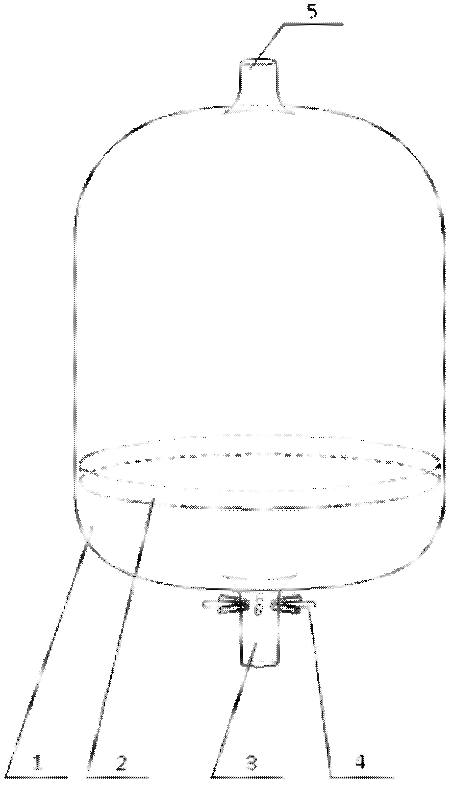
[0016] like figure 1 As shown, it discloses the PIV experimental particle blender based on the pneumatic tab technology of the present invention, including a blending tank 1, a filter disc 2, an air intake manifold 3, a pneumatic tab 4, and an air outlet pipe 5. The pneumatic tab 4 consists of a pneumatic tab nozzle and a jet flow control mechanism. The pneumatic protruding nozzles are arranged circumferentially around the intake manifold, and the number is selected according to the diameter of the intake manifold and the mixing effect, generally less than 8. The shape of the injection port of the pneumatic protruding nozzles can be circular, Ellipse, rectangle or any polygon. The axial direction...


PUM


Abstract

The invention discloses a particle image velocimetry (PIV) experimental particle mixing device based on a pneumatic lug technology, which comprises a mixing tank and a filtering element disk for containing PIV trace particles; the filtering element disk is arranged in the mixing tank; moreover, the mixing tank is respectively provided with an air-inlet main pipe and an air outlet pipe, the circumferential direction nearby the position of an outlet of the air-inlet main pipe is evenly distributed with pneumatic lugs, the pneumatic lugs comprise the jetting pipes of the pneumatic lugs and flow-jetting control mechanisms for controlling the jetting flow rate of the jetting pipes of the pneumatic lugs, and the jetting ports of the jetting pipes of the pneumatic lugs are arranged in a way of facing to a main flow area of the air-inlet main pipe; furthermore, the air inlets of the jetting pipes of the pneumatic lugs are communicated with bypass airflow; and moreover, the total pressure of airflow jetted by the jetting pipes of the pneumatic lugs is higher than the total pressure of airflow in the air-inlet main pipe. Therefore, flowing vortex is formed at the positions of the outlets of the jetting pipes by arranging the pneumatic lugs on the air-inlet main pipe according to the PIV experimental particle mixing device based on the pneumatic lug technology, so that the mixing effect of PIV particles in a particle mixer is improved.

Description

technical field [0001] The invention relates to a PIV experimental particle blender. Background technique [0002] The concentration of particles in PIV experiments is crucial to the success of PIV experiments. Especially for PIV experiments in direct-connected wind tunnels, how to ensure that the experimental particles can have a relatively stable particle concentration within a certain period of time has always been a technical difficulty in this field. At present, a solution is to install a bulky particle blender before the inlet of the experimental section, but due to the limitation of the diameter and distance of the intake manifold of the particle blender, the mainstream airflow cannot sufficiently impact the PIV tracer particles The cartridge tray is held so that the PIV particles do not blend well in the particle blender. Therefore, how to reduce the core area of ​​the potential flow of the intake manifold airflow and increase its sweeping ability within the limite...

Claims


Application Information

Patent Timeline
Patent Type & Authority Patents(China)
IPC IPC(8): B01F13/02G01M9/04B01F33/40
Inventor 徐惊雷顾瑞沙江马静俞凯凯莫建伟
Owner NANJING UNIV OF AERONAUTICS & ASTRONAUTICS
Learn More