Initial alignment method of permanent magnetic synchronous motor rotor of pure electric vehicle

A permanent magnet synchronous motor, pure electric vehicle technology, applied in motor generator control, electronic commutation motor control, control generator, etc. complex problems, to achieve the effect of simple and practical detection method, high detection accuracy, and simple detection equipment

Inactive Publication Date: 2012-06-20
ZHENGZHOU AIRCRAFT EQUIP
View PDF5 Cites 16 Cited by
  • Summary
  • Abstract
  • Description
  • Claims
  • Application Information

AI Technical Summary

Problems solved by technology

The existing method for determining the initial position of the rotor of a permanent magnet synchronous motor is to determine the initial position of the rotor after energizing a certain phase current of the motor to achieve an accurate positioning of the motor rotor position; the disadvantage is that the control system is relatively complicated and requires control software to determine the initial position of the rotor. Cooperate
Another method is to use the salient pole effect of permanent magnet synchronous motors to accurately identify the initial position of the motor rotor by adding high-frequency excitation current to the motor windings, but this method cannot be applied to surface-mounted permanent magnets without salient pole effects Synchronous motors have poor applicability to different types of motors, and the detection device is complicated

Method used


Image

  • Initial alignment method of permanent magnetic synchronous motor rotor of pure electric vehicle
  • Initial alignment method of permanent magnetic synchronous motor rotor of pure electric vehicle
  • Initial alignment method of permanent magnetic synchronous motor rotor of pure electric vehicle

Examples


Embodiment Construction

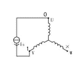
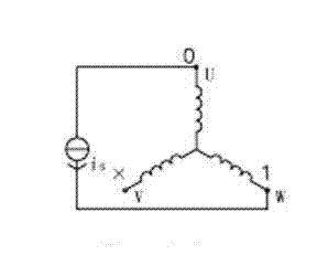
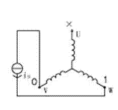
[0016] In the method for initial positioning of the rotor of a permanent magnet synchronous motor of a pure electric vehicle according to the present invention, a rotary transformer is pre-installed during motor manufacturing, and the U-phase, V-phase, and W-phase state signals are output by the rotary transformer for detection. During monitoring, the U-phase, V-phase, and W-phase state signals sent by the resolver have a total of six level states, such as Figure 1-1 to Figure 1-6 As shown, 01X, 0X1, X01, 10X, 1X0, and X10 indicate that the electric angle position of the motor rotor is six equal intervals, and each interval is an electrical angle of 60°. In Figure 1, 1 represents high level and 0 represents low level. level, X stands for floating.

[0017] Such as Picture 1-1 As shown, the state 01X means that the U phase of the resolver is connected to the negative pole of the DC power supply is, the V phase is connected to the positive pole of the DC power supply is, and t...


PUM


Abstract

The invention discloses an initial alignment method of a permanent magnetic synchronous motor rotor of a pure electric vehicle, comprising the following steps: 1, respectively detecting a deviation amount of a permanent magnetic synchronous motor between a zero position of a rotary transformer mounted on a motor axle and a mechanical zero position of the motor at six level states; 2, judging the deviation amount in the first step: if the deviation amount is smaller than the preset error, calculating an average value of the six deviation values as an initial position of the motor rotor; if the deviation amount is larger than the preset error, detecting an outlet sequence of the permanent magnetic synchronous motor and then repeating the above steps. The initial alignment method has the following advantages: 2, the detection method is simple and practical; 2 during the detection process, the motor is detected without being mounted on a testing stand; 3, the detection device is simple, a switch and a contactor set are needed and a frequency converter and a motor controller are not needed to detect; 4, the detection accuracy is high, the maximum initial alignment error by the method does not exceed +- 5 degree electrical angles; 5, the outlet sequence of the motor is detected by a certain logical relationship judgment.

Description

technical field [0001] The invention relates to a positioning method for a rotor of a permanent magnet synchronous motor after assembly, in particular to an initial positioning method for a permanent magnet synchronous motor rotor of a pure electric vehicle. Background technique [0002] At present, when controlling the permanent magnet synchronous motor for pure electric vehicles, the vector direction of the three-phase current synthetic magnetic field of the stator is controlled by the controller. In order to effectively control the stator magnetic field vector, accurate measurement of the rotor position is required. The existing method for determining the initial position of the rotor of a permanent magnet synchronous motor is to determine the initial position of the rotor after energizing a certain phase current of the motor to achieve an accurate positioning of the motor rotor position; the disadvantage is that the control system is relatively complicated and requires c...

Claims


Application Information

Patent Timeline
Patent Type & Authority Applications(China)
IPC IPC(8): H02P6/16H02P21/32
Inventor 史迪新阴卫国陈三成
Owner ZHENGZHOU AIRCRAFT EQUIP
Why Eureka
Try Eureka