Broadband Operating Waveguide Traveling Wave Power Synthesizing Amplifier

A power combiner and power amplifier technology, applied in waveguide devices, electrical components, connecting devices, etc., can solve problems such as inconsistent input signals, inconsistent output port phases of power dividers, and inconsistent microwave signal path lengths, etc., to achieve high Efficiency power synthesis, realizing power synthesis, and increasing the number of synthesis channels

Inactive Publication Date: 2014-10-08
SOUTH CHINA UNIV OF TECH +1
View PDF5 Cites 0 Cited by
  • Summary
  • Abstract
  • Description
  • Claims
  • Application Information

AI Technical Summary

Problems solved by technology

For the waveguide traveling wave power combining structure, none of the reported structures can solve a problem, that is, the phase of the output port of the power divider is inconsistent due to the inconsistency of the transmission path length of the microwave signal from the input port to the output of each coupling structure.
When the phases of the output ports of the power divider are inconsistent, the input reflection signal of the amplifier unit connected to the output port of the power divider will enter the other amplifier units, thereby affecting each other, making the input signals of each amplifier unit inconsistent, which will cause the amplifier unit The working state is inconsistent, which will seriously affect the stability and linearity of the power synthesis amplifier
It can be seen from this that the previously proposed traveling-wave power combining amplifier structure generally works near the frequency point of the in-phase (or inverting) output of the power divider, and is only suitable for narrow-band work.

Method used


Image

  • Broadband Operating Waveguide Traveling Wave Power Synthesizing Amplifier
  • Broadband Operating Waveguide Traveling Wave Power Synthesizing Amplifier
  • Broadband Operating Waveguide Traveling Wave Power Synthesizing Amplifier

Examples


Embodiment 1

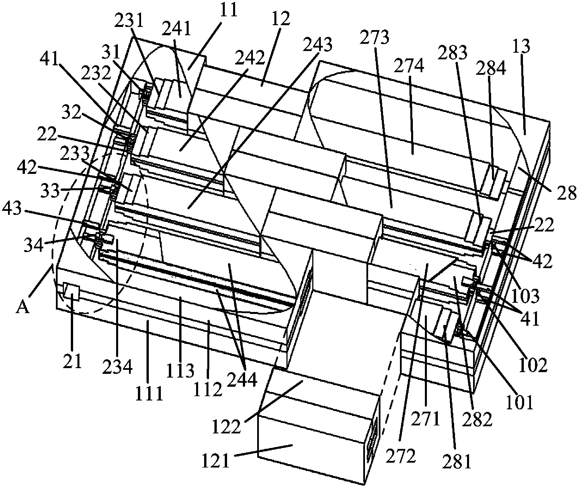
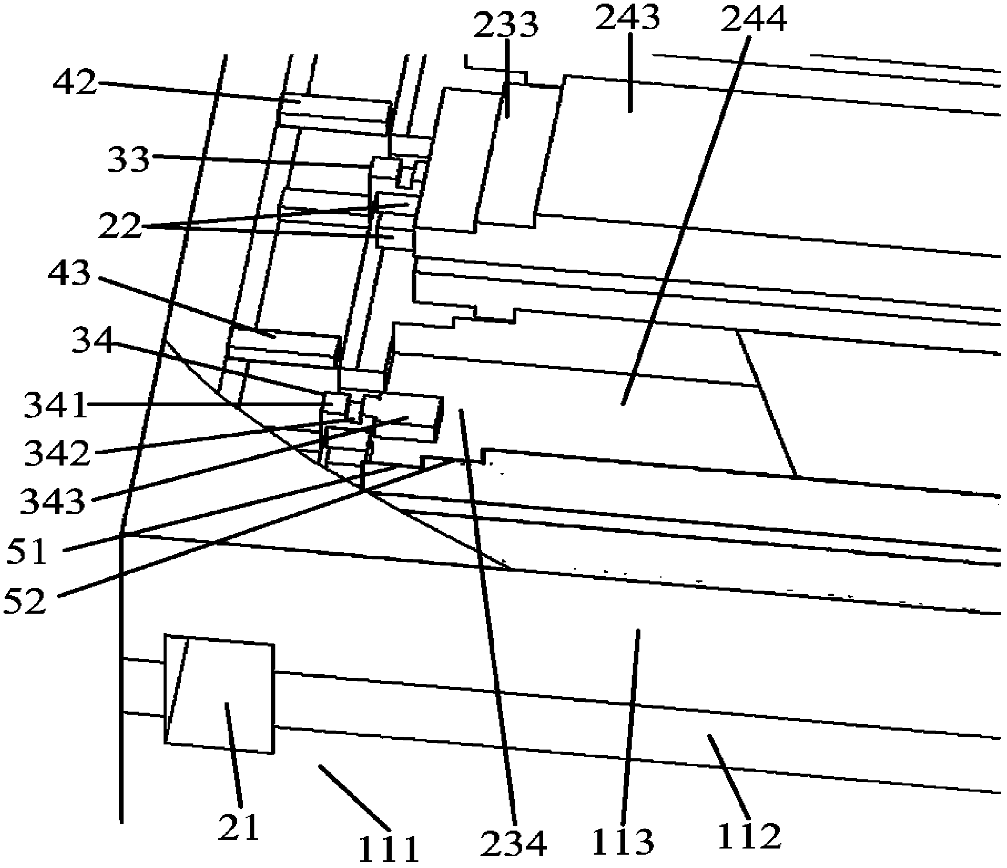
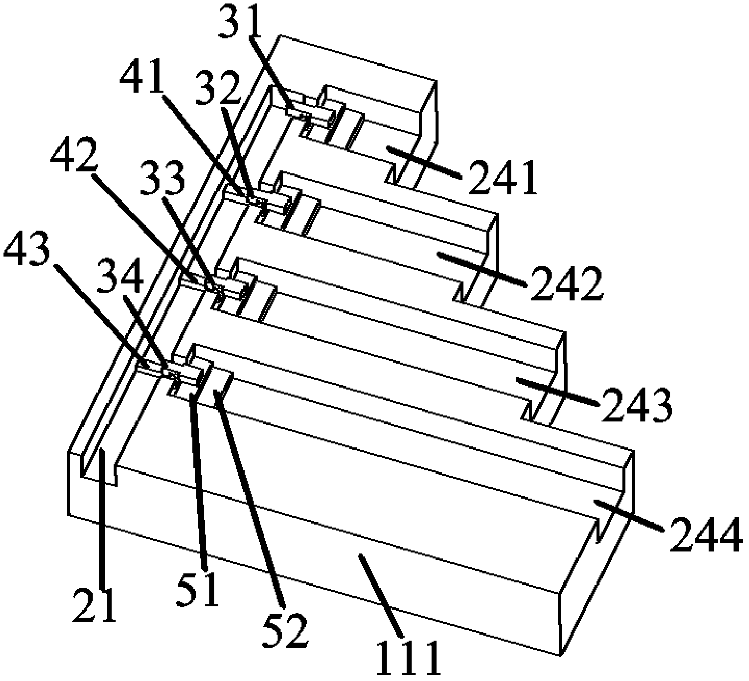
[0035] This embodiment uses a ridge waveguide probe type coupling structure to illustrate the basic idea of ​​the present invention. Such as figure 1 As shown in the perspective view of the synthesizing amplifier composed of ridge waveguide probe-type coupled broadband in-phase or anti-phase waveguide traveling-wave power dividers, the overall structure is composed of a power divider 11 , an amplifier module 12 and a power combiner 13 . The power combiner 13 is consistent with the power divider 11 in terms of structure, except that it is placed in the form of rotating butt joint with the power divider along the vertical direction. The power splitter 11 includes an input standard waveguide 21, a ridge waveguide probe type coupling structure 31-34, a matching diaphragm 41-43, a matching transition structure 231-234 from the ridge waveguide probe type coupling structure to an output waveguide, and an output waveguide 241 -244 and other parts. The power is input from the input w...

Embodiment 2

[0044] Such as Figure 7 As shown, the figure illustrates a microstrip probe-type coupled in-phase output power divider structure. The only difference between this embodiment and the first embodiment is that this embodiment uses a microstrip probe type coupling structure to illustrate the basic idea of ​​the present invention. The main difference between this structure and the ridge waveguide probe type coupling waveguide traveling wave power divider is that the form of the coupling structure is changed to a microstrip probe, correspondingly, a matching transition structure from the microstrip to the output waveguide is introduced. This structure still adjusts the output phase of the power splitter to be consistent by extending the output waveguide. The design principle of the microstrip probe is basically the same as that of the ridge waveguide probe structure. The matching transition structure from the microstrip to the output waveguide adopts the probe transition form. By...

Embodiment 3

[0046] Such as Figure 8 As shown, the figure illustrates a coaxial probe type coupling in-phase output power divider structure. The only difference between this embodiment and the first embodiment is that the coupling structure of the power divider is changed to a coaxial probe, and correspondingly, a matching transition structure from the coaxial to the output waveguide is introduced. This structure still adjusts the output phase of the power splitter to be consistent by extending the output waveguide. The design principle of the coaxial probe is basically the same as that of the ridge waveguide probe structure. The matching transition structure from the coaxial to the output waveguide adopts the probe transition form. By inserting the coaxial probe 261 on the wide side of the waveguide 262, a short-circuit surface is set at a certain distance from the probe to realize the transition from the coaxial to the waveguide 262. The waveguide 262 forms an output waveguide through...


PUM


Abstract

The invention discloses a wideband working waveguide traveling wave power synthesis amplifier comprising two wideband non-inverting or inverting waveguide traveling wave power distributors / synthesizers and at least one power synthesizer module. Each wideband non-inverting or inverting waveguide traveling wave power distributor / synthesizer consists of input waveguide, at least one stage of coupling structure and more than one output waveguide, as well as a matching transition structure connected with both the coupling structure and the output waveguide; each stage of coupling structure is arranged perpendicular to the traveling wave of the input waveguide, except the last stage of coupling structure, a matching diaphragm used for preventing an electromagnetic field from generating reflection in the wave guide during transmission in each stage of coupling structure is arranged at each stage of coupling structure; the output waveguide is arranged perpendicular to the input waveguide; the length of each output waveguide connected with each stage of coupling structure differs from that of others, and finally, output signals with the same amplitude and phase are achieved. The multi-way and efficient synthesis amplifier with wideband provided by the invention is applied to high-end and millimeter wave bands of the microwave.

Description

technical field [0001] The invention relates to a power synthesis technology for microwave and millimeter wave frequency bands, in particular to a waveguide traveling wave power synthesis amplifier capable of broadband operation. Background technique [0002] In the microwave and millimeter wave frequency bands, people generally use a power combining network to combine the output power of multiple solid-state devices to realize high-power solid-state devices. There are two types of power synthesis technology: oscillation synthesis and amplification synthesis, among which power synthesis amplifiers are widely used. Regardless of the type, the output power of multiple solid-state devices is synthesized through a power synthesis network to realize a high-power synthesis amplifier. The nature of the power combining network directly determines the performance of the synthesizing amplifier. Therefore, the focus of power combining technology research is mainly on the properties of...

Claims


Application Information

Patent Timeline
Patent Type & Authority Patents(China)
IPC IPC(8): H01P5/12
Inventor 褚庆昕龚志王颖康智勇
Owner SOUTH CHINA UNIV OF TECH
Why Eureka
Try Eureka