
Partial discharge detection pulse current sensor with self correcting function

A technology of partial discharge detection and pulse current, which is applied in the direction of testing dielectric strength, etc., can solve the problems of being unable to judge whether it is still in normal working condition, troublesome equipment operation, and inconvenient calibration of sensors, etc.

Inactive Publication Date: 2012-06-20
BAODING TIANWEI GRP CO LTD
View PDF4 Cites 7 Cited by
  • Summary
  • Abstract
  • Description
  • Claims
  • Application Information

AI Technical Summary

Problems solved by technology

[0002] At present, there are many kinds of sensors for partial discharge detection. Among them, the pulse current sensor is mainly used to detect the pulse current change on the grounding wire of the equipment. However, this type of sensor generally only has one output interface. When actually installing and calibrating, it is necessary to wind the transformer separately. As a calibration coil, calibration can only be performed by inputting a standard signal, and it will be inconvenient to calibrate again after the sensor is installed
In addition, this type of sensor has only one output interface, and it is impossible to judge whether it is still in a normal working state after long-term partial discharge inspection or partial discharge online monitoring and other actual use
It even needs to shut down the monitored equipment to make a judgment, which brings unnecessary trouble to the operation of the equipment

Method used


Image

  • Partial discharge detection pulse current sensor with self correcting function
  • Partial discharge detection pulse current sensor with self correcting function
  • Partial discharge detection pulse current sensor with self correcting function

Examples


Embodiment Construction

[0017] The present invention will be further described through the embodiments below in conjunction with the accompanying drawings.

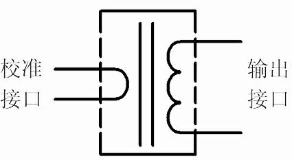
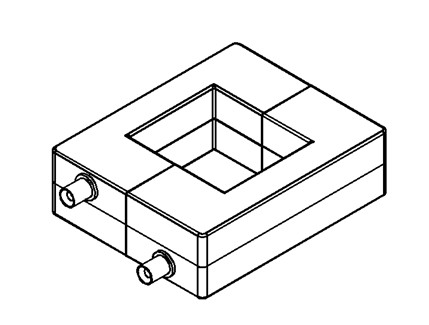
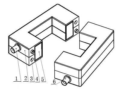
[0018] Partial discharge detection pulse current sensor with self-calibration function, the closed-loop magnetic core 5, output coil and calibration coil are arranged in the shell, and the partial discharge detection is carried out by inducing the current flowing through the magnetic core through the output coil wound on the closed-loop magnetic core. A calibration coil is added to the magnetic core to realize self-calibration and self-test functions, and a calibration interface 1 and an output interface 6 are provided, the calibration interface is connected to the calibration coil, and the output interface is connected to the output coil.

[0019] Said casing has various structures, including: the casing is an open rectangular structure or a closed circular structure, which is suitable for partial on-line inspection or partial on-line monitoring...


PUM


Abstract

The invention relates to a partial discharge detection pulse current sensor with a self correcting function, belonging to the technical field of sensors for detection. The technical scheme of the partial discharge detection pulse current sensor is as follows: a closed-loop magnetic core (5), an output coil and a correcting coil are arranged in a shell, the output coil wound on the closed-loop magnetic core is used for inducing a current flowing through the closed-loop magnetic core to carry out partial detection, the correcting coil is additionally arranged on the closed-loop magnetic core so as to be used for realizing self correcting and self detection functions, and the partial discharge detection pulse current sensor is provided with a correcting interface (1) and an output interface (6), the correcting interface is connected with the correcting coil, and the output interface is connected with the output coil. The shell is of various structures, comprising an opening rectangle structure and a closed round structure, and is suitable for partial discharge online routing inspection or local discharge online monitoring. The partial discharge detection pulse current sensor disclosed by the invention has the beneficial effects of realizing self correcting and self detecting functions, being suitable for local discharge online inspection or partial discharge online monitoring, and being convenient and exact.

Description

technical field [0001] The invention relates to a partial discharge detection pulse current sensor with a self-calibration function, belonging to the technical field of detection sensors. Background technique [0002] At present, there are many kinds of sensors for partial discharge detection. Among them, the pulse current sensor is mainly used to detect the pulse current change on the grounding wire of the equipment. However, this type of sensor generally only has one output interface. When actually installing and calibrating, it is necessary to wind the transformer separately. As a calibration coil, calibration can only be performed by inputting a standard signal, and it will be inconvenient to calibrate again after the sensor is installed. In addition, this type of sensor has only one output interface, and it is impossible to judge whether it is still in a normal working state after long-term partial discharge inspection or partial discharge online monitoring and other ac...

Claims


Application Information

Patent Timeline
Patent Type & Authority Applications(China)
IPC IPC(8): G01R31/12
Inventor 何平刘大永杜玉新张鹏飞高常海王京保
Owner BAODING TIANWEI GRP CO LTD
Learn More