Piston reset tool for disc brake

A technology of disc brakes and pistons, applied in the manufacture of tools, hand-held tools, etc., can solve the problems of large differences in the thickness of the friction plate, cumbersome operation process, and difficulty in piston reset, and achieve overcoming blockage, convenient use, and simple structure Effect

Inactive Publication Date: 2012-06-20
CHERY AUTOMOBILE CO LTD
View PDF10 Cites 7 Cited by
  • Summary
  • Abstract
  • Description
  • Claims
  • Application Information

AI Technical Summary

Problems solved by technology

[0002] At present, when replacing the friction lining or brake disc of a disc brake, it is often encountered that the piston is difficult to reset due to the automatic adjustment of the clearance of the piston, which leads to the situation that the friction lining or brake disc cannot be assembled after replacement, especially when the friction lining is worn. Replace the friction plate after reaching the limit. Due to the large difference in thickness between the new and old friction plates, the displacement required for the piston to reset is correspondingly large, and the difficulty in replacement is very prominent.
The current way to reset the piston is to loosen the oil drain screw on the brake caliper, and then use the method of tapping or using the principle of leverage to support the piston with the help of a guide pin to pry to reset the piston. These two methods can easily lead to the rupture of the piston dust cover. Or the guide deformation occurs, and after the piston is reset and the friction plate is replaced, the brake system must be exhausted, and the operation process is very cumbersome.

Method used


Image

  • Piston reset tool for disc brake
  • Piston reset tool for disc brake
  • Piston reset tool for disc brake

Examples


Embodiment 1

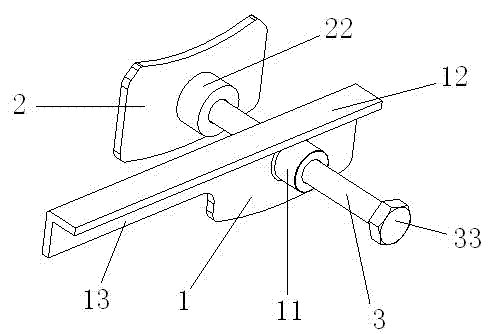
[0019] Such as figure 1 As shown, the outer push plate 1, the inner push plate 2 and the screw rod 3 of the disc brake piston reset tool of the present embodiment, wherein the outer push plate 1 is equipped with a threaded sleeve 11, and a threaded hole is arranged in the threaded sleeve 11; the outer push plate 1 has a horizontal fold 12 on the top surface, and an extended armrest 13 is provided on the side.

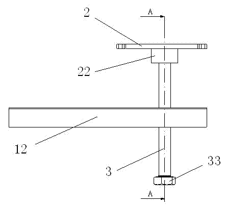
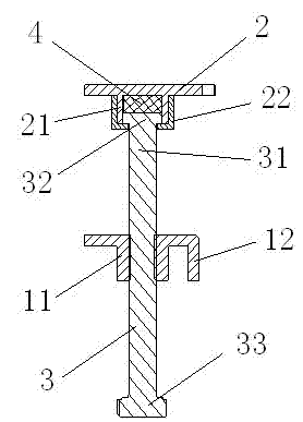
[0020] Such as figure 2 , 3 As shown, the side of the inner push plate 2 is provided with an annular limit seat 21, and the limit seat 21 is provided with an external thread, and a hollow locking cap 22 is installed through thread fit, and the locking cap 22 is far away from the inner push plate. The side of the screw rod is provided with a through hole; the pressing end 31 of the screw passes through the threaded hole of the threaded sleeve 11 and the through hole of the locking cap 22 in turn, and extends into the locking cap 22; the end of the pressing end 31 of t...


PUM


Abstract

The invention provides a piston reset tool for a disc brake, wherein the piston reset tool has a simple structure and is convenient to use and is used for conveniently replacing a friction disc or a brake disc of the disc brake. The piston reset tool for the disc brake comprises an outer push plate, an inner push plate and a screw. The outer push plate is provided with a threaded hole. A hollow locking cap is arranged on the lateral surface of the inner push plate. The lateral surface of the locking cap, which is far away from the inner push plate, is provided with a through hole. The pressing end of the screw sequentially passes through the threaded hole of the outer push plate and the through hole of the locking cap and extends into the locking cap of the inner push plate. When the piston reset tool for the disc brake is in use, the inner push plate and the outer push plate are placed between a piston of the disc brake and callipers and the inner push plate is gradually far away from the outer push plate by rotating the screw, so that the distance between the callipers and the piston is lengthened, the retention force of a sealing ring of the callipers and the retardation of brake fluid in a brake pipeline system are overcome, the brake fluid is pushed back into a brake fluid storage tank and the aims of resetting the piston and draining the redundant brake fluid in a cylinder hole of a wheel cylinder of the callipers into the brake fluid storage tank are fulfilled.

Description

technical field [0001] The invention belongs to the technical field of automobile assembly, and in particular relates to a special tool for solving the difficulty of resetting when replacing a friction plate or a brake disc of a disc brake. Background technique [0002] At present, when replacing the friction lining or brake disc of a disc brake, it is often encountered that the piston is difficult to reset due to the automatic adjustment of the clearance of the piston, which leads to the situation that the friction lining or brake disc cannot be assembled after replacement, especially when the friction lining is worn. Replace the friction plate after the limit is reached. Due to the large difference in thickness between the new and old friction plates, the displacement required for the piston to reset is relatively large, and the difficulty in replacement is very prominent. The current way to reset the piston is to loosen the oil drain screw on the brake caliper, and then ...

Claims


Application Information

Patent Timeline
Patent Type & Authority Applications(China)
IPC IPC(8): B25B27/00
Inventor 贾占辉章余发李晓明葛宜银
Owner CHERY AUTOMOBILE CO LTD
Why Eureka
Try Eureka