
Regenerative thermal oxidization system and method for operating same

An exhaust gas purification system and thermal storage combustion technology, applied in the direction of combustion method, combustion type, combustion equipment, etc., can solve the problems of VOC concentration decrease, change, fuel cost increase, etc., and achieve the effect of mitigating the impact

Active Publication Date: 2012-06-13
SINTOKOGIO LTD
View PDF9 Cites 13 Cited by
  • Summary
  • Abstract
  • Description
  • Claims
  • Application Information

AI Technical Summary

Problems solved by technology

[0006] However, in the prior art, such as Figure 5 As shown, there is the following problem: in the case of closing the atmosphere opening gate 8, the RTO (although the label in the figure is "B", but the label will be omitted below) is completely connected with the production equipment A by using pipelines, so that the entrance of the RTO The static pressure change when the gate 9 or the outlet gate (not shown) is switched is transmitted to the production equipment through the pipeline
In this case, there is a problem that the air volume of the exhaust gas from the production equipment changes depending on the production situation, and there is a possibility that the exhaust gas leaks from the open duct to the atmosphere and attracts the atmosphere (air)
Therefore, there is a problem that the exhaust gas is diluted to lower the VOC concentration, which leads to an increase in fuel costs

Method used


Image

  • Regenerative thermal oxidization system and method for operating same
  • Regenerative thermal oxidization system and method for operating same
  • Regenerative thermal oxidization system and method for operating same

Examples


Embodiment Construction

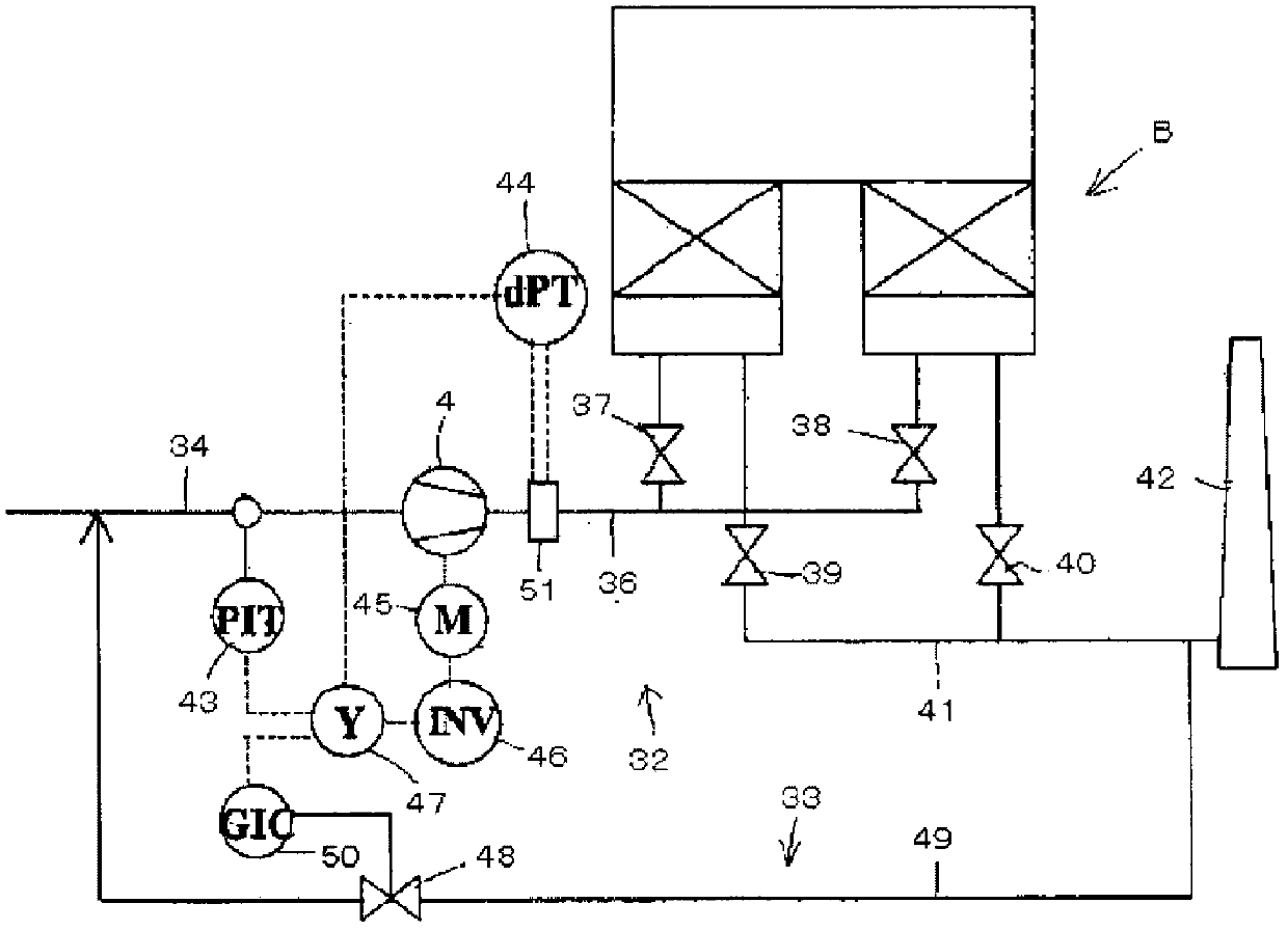
[0022] Embodiments of the present invention will be described below based on the drawings. Here, the same reference numerals are used for the same or similar components, and their repeated descriptions are omitted. The RTO according to one embodiment of the present invention, and the structure of the suction duct device for supplying exhaust gas from the production equipment to the RTO are as follows: figure 1 As shown, in the case of suction from two or more locations, air opening ducts 2, 22 that are always open to the atmosphere are provided on the secondary exhaust side of the exhaust blowers 1, 21 of the production facilities A1, A2. In addition, control gates 5, 25 (gates with adjustable openings) are provided between the air-opening ducts 2, 22 and the blower 4 for RTO and on each exhaust line from each device.

[0023] When the exhaust air volume from the production equipment A1 and A2 reaches the maximum, the overall suction air volume is adjusted by opening the con...


PUM


Abstract

Provided is a regenerative thermal oxidization system which solves the problem that a regenerative thermal oxidizer (RTO) is completely connected to production equipment by a duct when a damper open to the atmosphere is closed and, accordingly, a static pressure fluctuation generated when an inlet or outlet damper of the RTO is switched is transmitted to the production equipment via the duct, as well as the problem that there is a possibility that a duct open to the atmosphere, which is installed instead of the damper open to the atmosphere, functions as an atmospheric buffer and, accordingly, the amount of exhaust gas from the production equipment varies depending on the amount of production, and the leakage of the exhaust gas from the duct open to the atmosphere and the suction of atmospheric air occur. The regenerative thermal oxidization system is provided with a differential pressure transmitter whereby a duct open to the atmosphere, which is installed in an intake duct that connects the blower of the regenerative thermal oxidizer (RTO) and the exhaust blower of production equipment that generates exhaust gas, is connected to the control damper or the air blower operation inverter of the RTO, said damper or inverter being disposed between the differential pressure transmitter and the blower of the RTO.

Description

technical field [0001] The present invention relates to a thermal storage combustion exhaust gas purification system and its operating method. The thermal storage combustion exhaust gas purification system includes a regenerative thermal exhaust purification device (Regenerative Thermal Oxidizer) (hereinafter referred to as RTO), Suction duct device for mitigating static pressure fluctuations corresponding to air volume fluctuations during operation of combustion-type exhaust gas purification systems. [0002] More specifically, it relates to a regenerative combustion type exhaust gas purification system and an operation method thereof provided with a suction duct device, and for the suction duct device, the suction duct at the time of gate switching in order not to apply RTO to the production equipment which is the source of exhaust gas generation Influenced by fluctuations in static pressure, an air-opening duct is installed in the suction duct, and the suction duct connects...

Claims


Application Information

Patent Timeline
IPC IPC(8): F23G7/06F23G5/50F23L17/00
CPCF23G7/068F23G2900/70601
Inventor 鸟田智弘
Owner SINTOKOGIO LTD
Learn More