Connector and manufacture method thereof

A connector and elastic connection technology, which is applied in the direction of connection, fixed connection, contact piece manufacturing, etc., can solve the problems of high total cost, cost waste, low material utilization rate, etc., and achieve convenient processing, reduce production cost, and connector structure simple effect

Inactive Publication Date: 2012-06-13
HUIZHOU SPEED WIRELESS TECH CO LTD
View PDF7 Cites 2 Cited by
  • Summary
  • Abstract
  • Description
  • Claims
  • Application Information

AI Technical Summary

Problems solved by technology

The connector needs to open expensive metal molds for stamping, and some products need to be heat-treated and shaped, and then fully gold-plated
Although the cost of this type of connector is lower than that of the POGOPIN structure, more than a dozen such connectors are often used in a mobile phone, and the internal space of the mobile phone varies. In order to adapt to this space change, traditional Once the hardware mold is opened, it can only meet the production of one type of spring. If the height of the space inside the mobile phone changes, another mold can only be opened, and the total cost is still relatively high.
On the other hand, the processing method of die stamping hardware has a low material utilization rate, only about 40%.
image 3 for figure 2 The schematic diagram of the processing of the connector shown in the figure shows that the total width of the strip is L, and the shrapnel is designed side by side in the length direction of the strip. It can be seen from the figure that the material utilization rate of the shrapnel is only about 30% during the production process. , other materials become waste, and the cost waste is very serious

Method used


Image

  • Connector and manufacture method thereof
  • Connector and manufacture method thereof
  • Connector and manufacture method thereof

Examples


Embodiment Construction

[0021] In order to facilitate the understanding of those skilled in the art, the present invention will be described in detail below with reference to the drawings and embodiments.

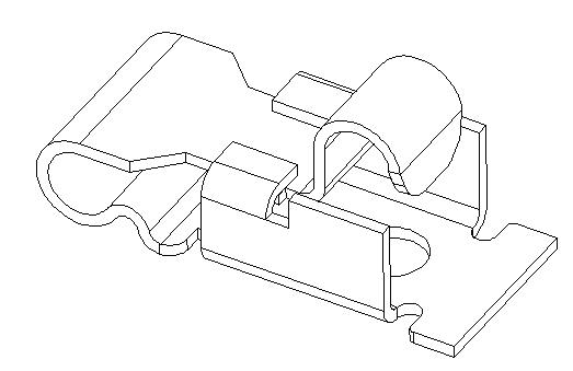
[0022] Such as figure 1 As shown, the connector disclosed by the present invention is in the form of a horizontal U-shape as a whole, and the lower arm of the U-shape is longer than the upper arm. The lower arm is bent upwards and inwards from the end to form an arched support part 10. The arched support part 10 is approximately an isosceles triangle, and the corners between the two waists are arcs to avoid sharp scratches; the end of the upper arm The elastic connection part 20 corresponding to the support part 10 is formed by arching from the bottom to the top, and the elastic connection part 20 is provided with a protrusion 21 for contacting the connected part. When in use, the elastic connecting part 20 is compressed, and with the help of the elasticity generated at the rear part, it will be ...


PUM


Abstract

The invention relates to a connector which is integrally shaped as a transverse U, the lower arm of the U shape is upwards and inwards bent from an end head to form an arch support part, the arch support part is approximately shaped as an isosceles triangle, included angle parts of two middles of the isosceles triangle are arcs; and the end head of the upper arm of the U shape is arched from the downside to the upside to form an elastic connecting part corresponding to the support part. During the use, the elastic connecting part is compressed and is in tightly contact with a connected member by means of the elasticity generated by the rear part of the elastic connecting part. The connector has the advantages of reliable performance, simple structure and convenience for processing. The connector can be formed by adopting directly bending and then cutting a width-fixed material belt without nearly generating wastes in the production process, thus metal materials and costs of manpower, transportation and the like are saved, and economic and social benefits can be great.

Description

[0001] technical field [0002] The invention relates to a connector, in particular to a connector used to connect two circuit boards on an electronic product. Background technique [0003] The connector (small connector) used to connect the antenna and the PCB board on the mobile phone generally has the following forms: [0004] 1. POGOPIN connection form, such as figure 1 shown. The advantage of this connector is to save space and size, but the cost is relatively high. When in use, its larger end is welded on the PCB, and the other end is compressed by the compression spring 3, so that the component 1 is connected to the feed point of another PCB. However, for the mobile phone antenna, its large end is welded on the PCB, and component 1 is on the feed point of the FPC of the mobile phone antenna. When it is pressed against the FPC, it is easy to break the gold finger of the FPC; Due to the need for electroplating and other reasons, the impedance will occasionally becom...

Claims


Application Information

Patent Timeline
IPC IPC(8): H01R13/24H01R12/00H01R12/52H01R12/55H01R43/16
Inventor 张子飞
Owner HUIZHOU SPEED WIRELESS TECH CO LTD
Why Eureka
Try Eureka