
Method for examining memory code of printed circuit board

A printed circuit board, code inspection technology, applied in static memory, instruments, etc., can solve problems such as increasing operating time

Inactive Publication Date: 2012-06-13
SHENZHEN CHINA STAR OPTOELECTRONICS TECH CO LTD
View PDF5 Cites 3 Cited by
  • Summary
  • Abstract
  • Description
  • Claims
  • Application Information

AI Technical Summary

Problems solved by technology

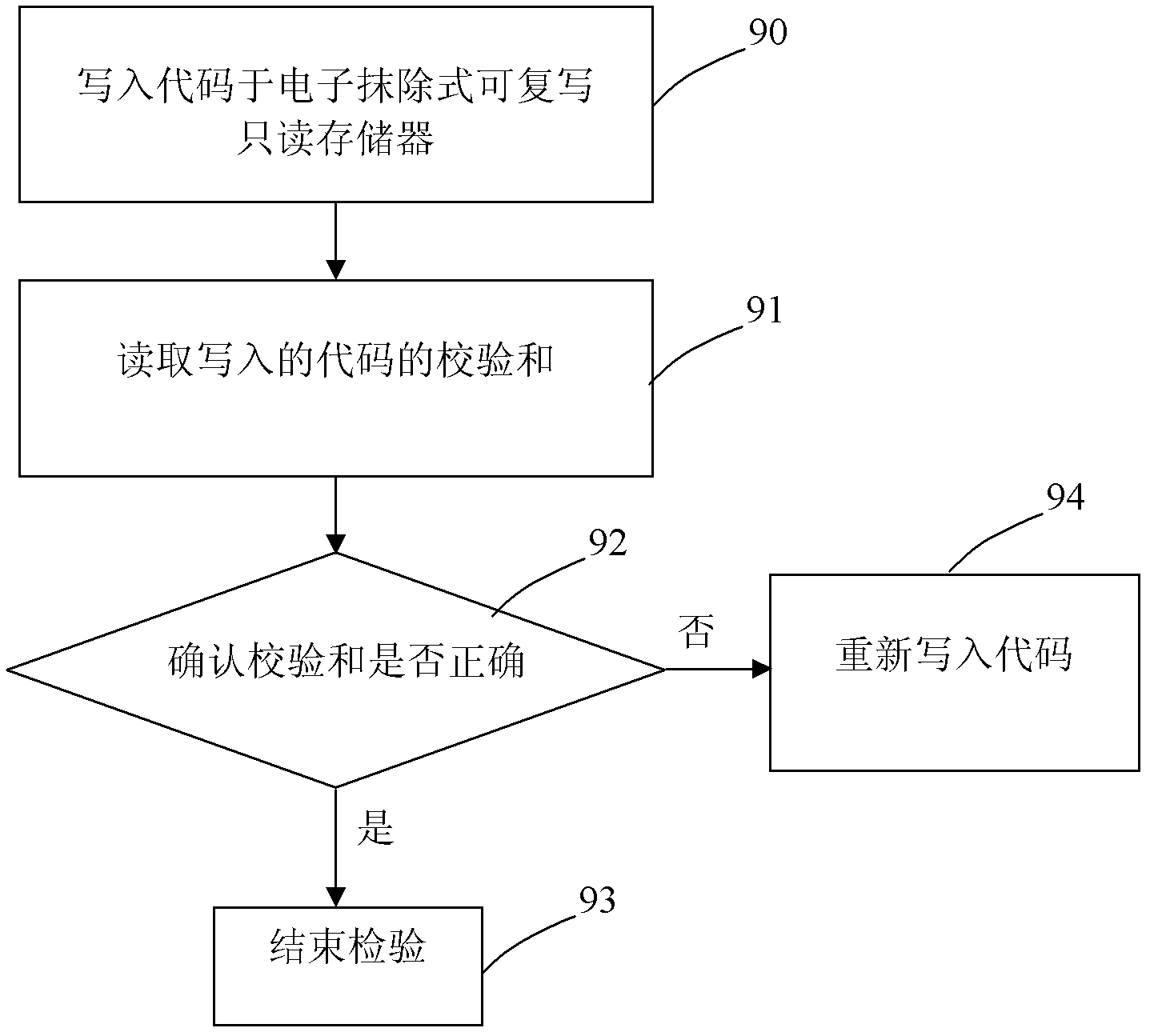
[0007] The main purpose of the present invention is to provide a memory code inspection method of a printed circuit board, which will solve the problem that the existing memory code inspection method of a printed circuit board must be combined with a computer and a jig to increase the working time

Method used


Image

  • Method for examining memory code of printed circuit board
  • Method for examining memory code of printed circuit board
  • Method for examining memory code of printed circuit board

Examples


Embodiment Construction

[0022] In order to make the above objects, features and advantages of the present invention more comprehensible, preferred embodiments of the present invention are exemplified below and described in detail in conjunction with the accompanying drawings. Furthermore, the directional terms mentioned in the present invention, such as "up", "down", "front", "back", "left", "right", "inside", "outside", "side", etc., It is only for orientation with reference to the attached drawings. Therefore, the directional terms used are used to illustrate and understand the present invention, but not to limit the present invention.

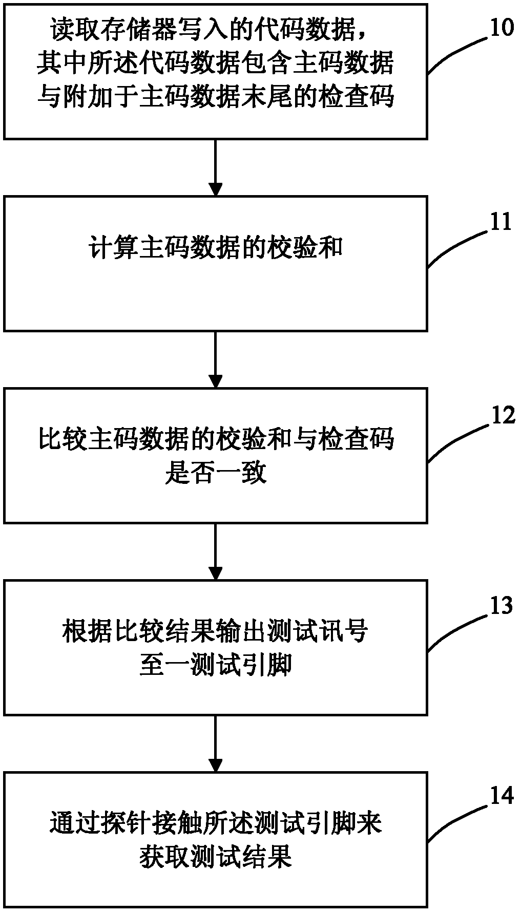
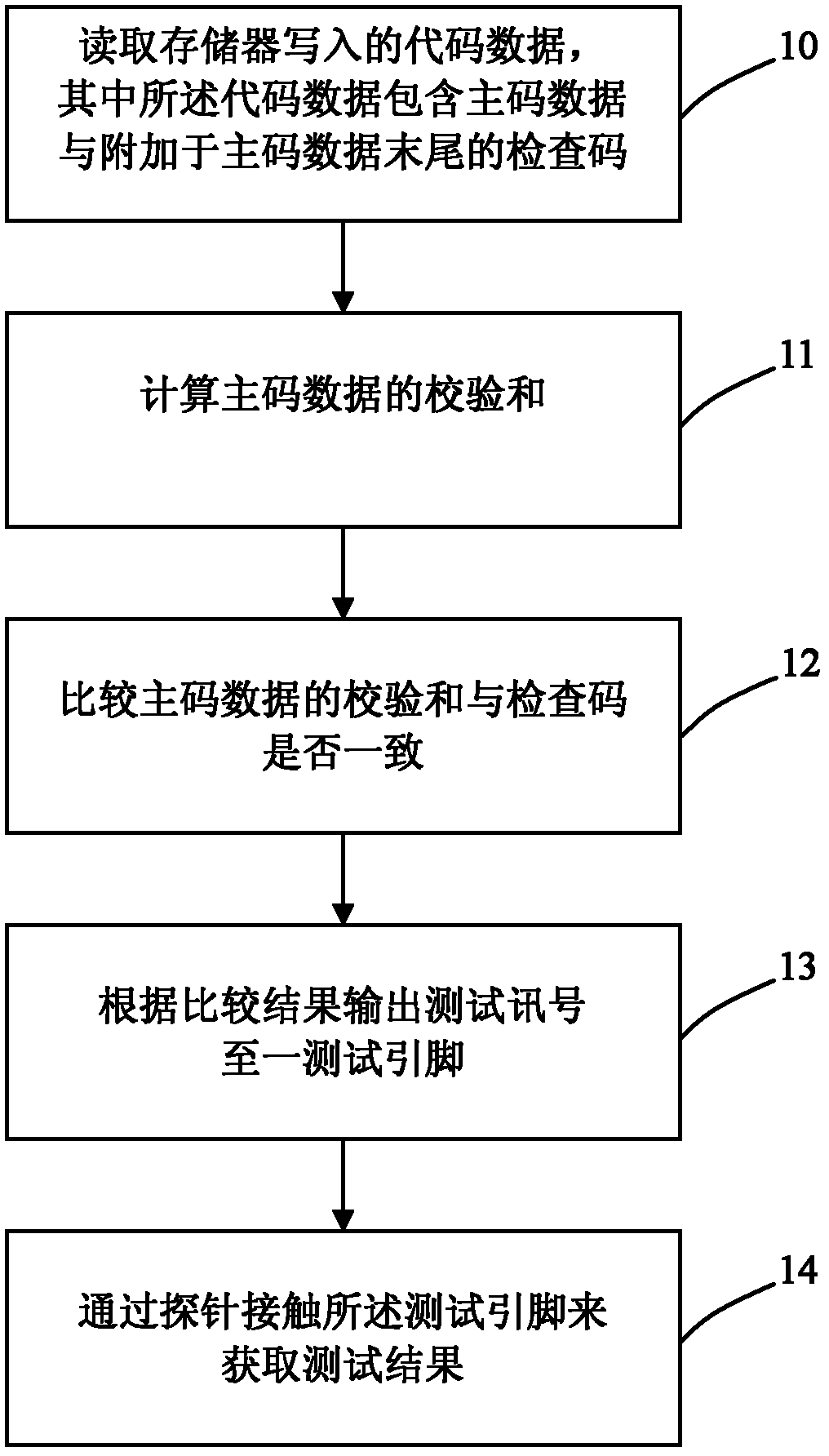
[0023] Please refer to figure 2 as shown, figure 2 It is a flow chart of a preferred embodiment of the memory code checking method of the printed circuit board of the present invention. Such as figure 2 As shown, the memory code inspection method of the printed circuit board of the present invention comprises the following steps:

[0024] S10: Read the code...


PUM


Abstract

The invention discloses a method for examining a memory code of a printed circuit board, which comprises the following steps: adding a checking code at data end of the code, after writeing in a memory, calculating a checksum of the data of a main code part by a timing controller, comparing the calculated checksum and the checking code, outputting a test pin to a probe for displaying the comparison result to reach the purpose of examining whether the write-in code is correct or not. The method of the invention is capable of enhancing the work efficiency of the write-in code examination in the memory.

Description

【Technical field】 [0001] The invention relates to a method for checking printed circuit boards, in particular to a method for checking memory codes of printed circuit boards. 【Background technique】 [0002] In the prior art, the driving system of the liquid crystal display uses a timing controller (Timing controller) to read the code (code) written in the read-only memory to perform timing (Timing) and dimming (Dimming) on ​​the liquid crystal panel. , Over Drive (Over Drive) and Gamma correction (Gamma correction) and other control technologies. In order to improve the production efficiency of the hardware of the driving system, the industry usually writes the code in the aforementioned read-only memory in advance, and then installs it on the surface of the printed circuit board together with other components through SMT and DIP technology, and finally prints the code on the surface of the printed circuit board. Confirm the code when the circuit board undergoes electrical ...

Claims


Application Information

Patent Timeline
IPC IPC(8): G11C29/08
CPCG11C29/08G11C29/00G11C29/42
Inventor 林柏伸廖良展吴宇
Owner SHENZHEN CHINA STAR OPTOELECTRONICS TECH CO LTD
Learn More