
Circular cooler and unit static sealing device thereof

A technology of static sealing device and annular cooler, which is applied in the direction of engine sealing, engine components, mechanical equipment, etc., can solve the problems of easy damage to the lower flat plate 112 of the sealing rubber trolley, damage to the sealing rubber and the trolley body, etc. Complete unloading effect, lower maintenance cost, lower maintenance frequency effect

Active Publication Date: 2012-06-13
ZHONGYE-CHANGTIAN INT ENG CO LTD
View PDF5 Cites 1 Cited by
  • Summary
  • Abstract
  • Description
  • Claims
  • Application Information

AI Technical Summary

Problems solved by technology

[0007] However, limited by its own structure, the existing static sealing device of the trolley unit can easily cause the sealing rubber 16 and the lower plate 112 of the trolley to be easily damaged during the operation of the trolley.
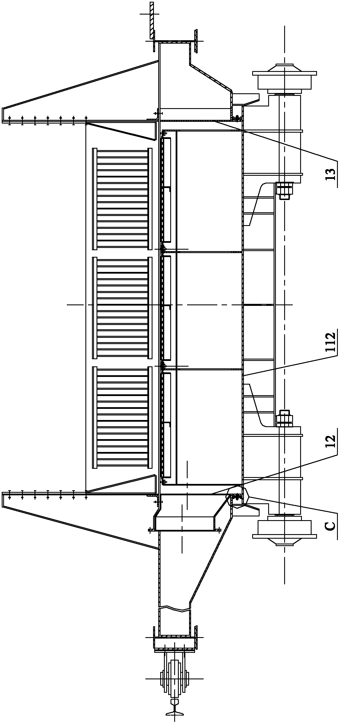
combine Figure 4 As shown, since the sealing fit is formed on the horizontal plate surface of the lower plate 112 of the trolley, it is obvious that when the lower plate of the sealing fit is partially adhered and accumulated with sintered ore after unloading, the lower plate will be formed after the trolley is reset and closed. Materials are sandwiched between the flat plate 112 and the sealing rubber 16, thereby damaging the sealing rubber and the trolley body

Method used


Image

  • Circular cooler and unit static sealing device thereof
  • Circular cooler and unit static sealing device thereof
  • Circular cooler and unit static sealing device thereof

Examples


Embodiment Construction

[0038] The core of the present invention is to provide a unit static sealing device with optimized structure to effectively solve the problem of residual minerals trapped between the sealing element and the lower plate of the trolley, and to ensure the working stability of the whole machine.

[0039] Without loss of generality, this embodiment will be described in detail below in conjunction with the accompanying drawings of the specification.

[0040] In this article, the orientation words inside and outside used for the inner sealing plate of the trolley and the outer sealing plate of the trolley are defined based on the center of the ring cooler, and the front and back of the relevant position words are the rotation of the ring cooler. The direction is defined on the basis. It should be understood that the use of the localizers such as inside, outside, before, and after does not limit the scope of protection claimed in this application.

[0041] In this embodiment, the basic func...


PUM


Abstract

The invention discloses a unit static sealing device for a circular cooler. The unit static sealing device comprises a trolley lower layer flat plate, a trolley inner side sealing plate, a trolley outer side sealing plate, a rear edge of a front support beam and a front edge of a rear support beam, wherein the trolley inner side sealing plate, the trolley outer side sealing plate, the rear edge of the front support beam and the front edge of the rear support beam are respectively form four continuous sealing edges with the periphery of the trolley lower layer flat plate; the four continuous sealing edges comprise a rigid protruding ring and an elastic sealing ring; the rigid protruding ring is surrounded and fixedly arranged on the upper surface of the trolley lower layer flat plate; the elastic sealing ring is surrounded and fixedly arranged on the trolley inner side sealing plate, the trolley outer side sealing plate, the rear edge of the front support beam and the front edge of therear support beam; and under the trolley sealing state, the lower surface of the elastic sealing ring props against the upper edge of the rigid protruding ring in a sealing mode. According to the invention, the problem that residual mineral aggregates are clamped between a sealing element and the trolley lower layer flat plate is solved, and the work stability of the whole machine is ensured. On the basis, the invention also provides the circular cooler with the unit static sealing device.

Description

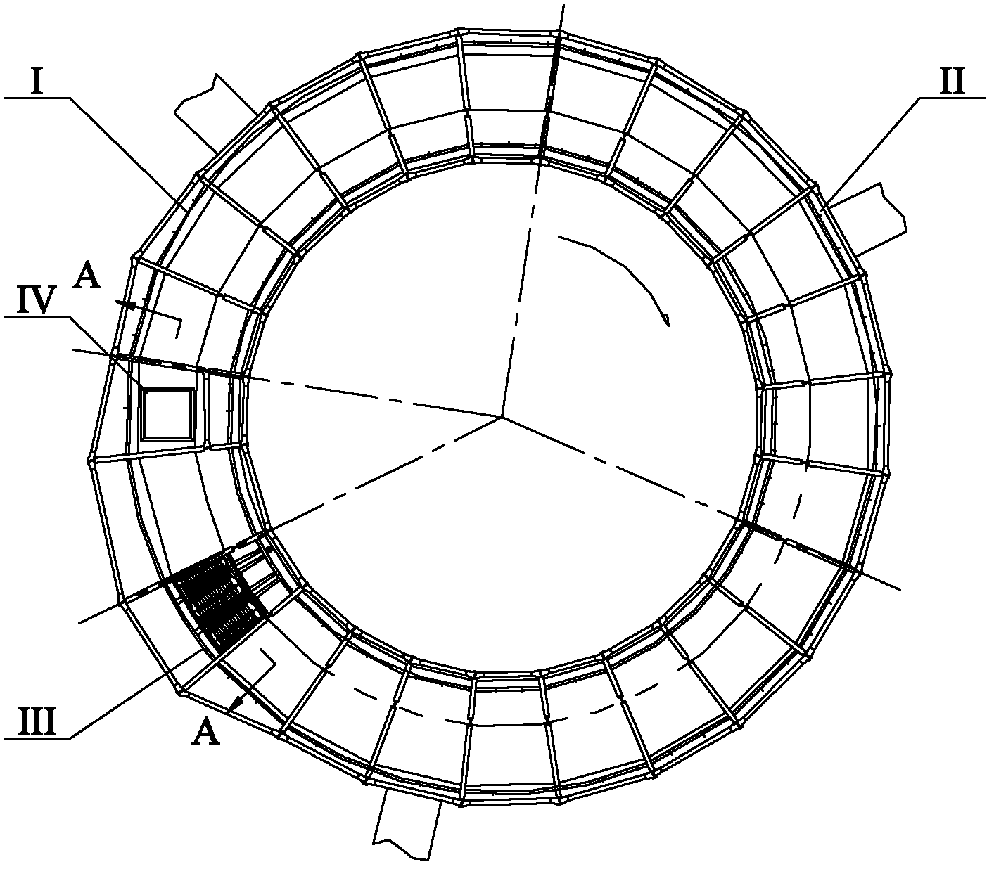
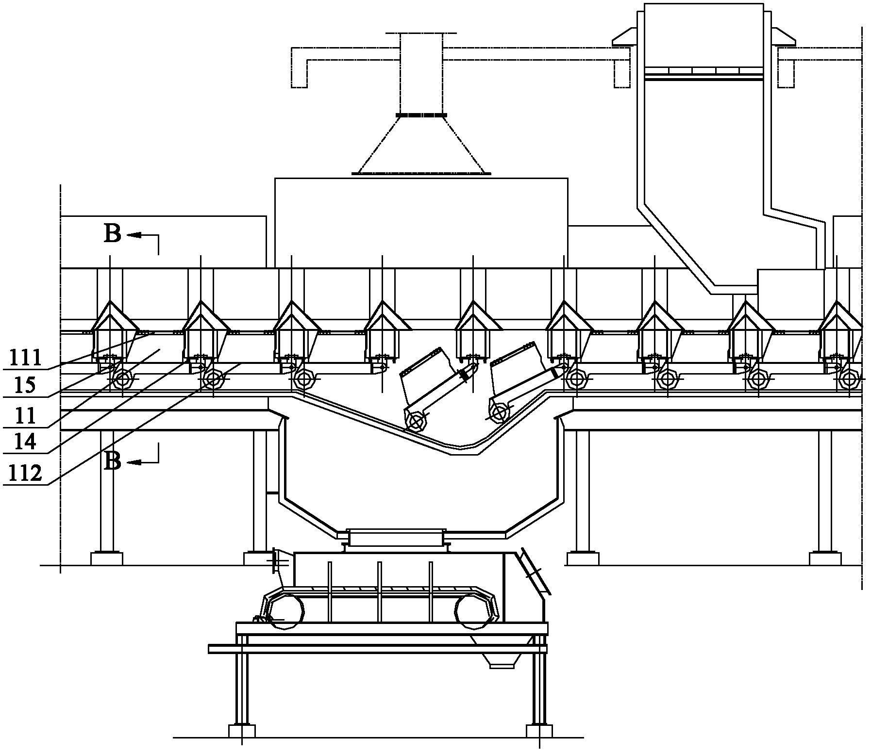
Technical field [0001] The invention relates to the field of steel smelting, in particular to an annular cooler and its unit static sealing device. Background technique [0002] Circulating coolers are used in iron and steel enterprises to cool sintered high-temperature materials. The annular cooler has a circular ring shape as a whole, which is divided into high temperature zone I, medium temperature zone II, low temperature zone III and non-cooling zone IV along the circumferential direction. During operation, the mineral material to be cooled is injected into each ring cooler trolley from the loading station in the non-cooling zone, and after entering the cooling zone, the mineral material is cooled by pressure wind, and then each ring cooler trolley enters the non-cooling The unloading station in the zone completes cooling and unloading. [0003] See figure 1 , figure 2 with image 3 ,among them, figure 1 Is the overall structure diagram of the ring cooler, figure 2 for fig...

Claims


Application Information

Patent Timeline
Patent Type & Authority Applications(China)
IPC IPC(8): F27D15/02F16J15/06F16J15/10
Inventor 王俊杰汤清铭邓志宏
Owner ZHONGYE-CHANGTIAN INT ENG CO LTD
Learn More