
Aeration system

A technology of air source and oxygen source, applied in the field of aeration system, can solve the problems of high oxygen price, inability to combine advantages, investment and operation cost risks, etc., and achieve the effect of reducing costs and improving sewage treatment capacity

Inactive Publication Date: 2012-06-13
成都绿水科技有限公司
View PDF4 Cites 9 Cited by
  • Summary
  • Abstract
  • Description
  • Claims
  • Application Information

AI Technical Summary

Problems solved by technology

However, due to the high price of oxygen, the large investment in oxygen generators, and the need for specialized technical operation and management, the use of pure oxygen aeration has been limited since it was proposed by the United States' Union Carbon Corporation in 1934.
[0007] In addition, in the prior art, air aeration and pure oxygen aeration are carried out according to their respective design calculation systems, and the models and capacities of aeration and mass transfer equipment are also completely different. , both compare the two in opposition and make an either-or choice, and cannot combine the advantages of the two
Moreover, the comparison of operating costs between pure oxygen aeration and air aeration is still a matter of debate, so designers will be in a dilemma when choosing an aeration scheme. If air aeration is used, the sewage When the treatment load fluctuates greatly and the scale of sewage treatment increases, new land and large sums of money are needed for reconstruction and expansion. If pure oxygen aeration is used, there will be risks in investment and operating costs under unpredictable conditions in the future.

Method used


Image

  • Aeration system
  • Aeration system
  • Aeration system

Examples


Embodiment Construction

[0027] The following will clearly and completely describe the technical solutions in the embodiments of the present invention with reference to the accompanying drawings in the embodiments of the present invention. Obviously, the described embodiments are only some of the embodiments of the present invention, not all of them. Based on the embodiments of the present invention, all other embodiments obtained by persons of ordinary skill in the art without creative efforts fall within the protection scope of the present invention.

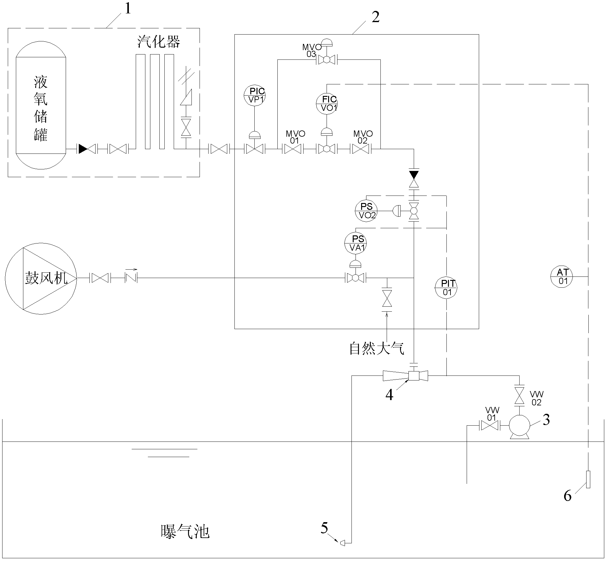
[0028] The aeration system provided by the embodiment of the present invention includes: an air source, an air supply control device, a power water pump, an ejector, and a synergistic nozzle, wherein: the air source includes an air source and an oxygen source, and one end of the air supply control device is connected to The air source, the other end is connected to the suction hole of the ejector, which is used to control the air source and air flow in...


PUM


Abstract

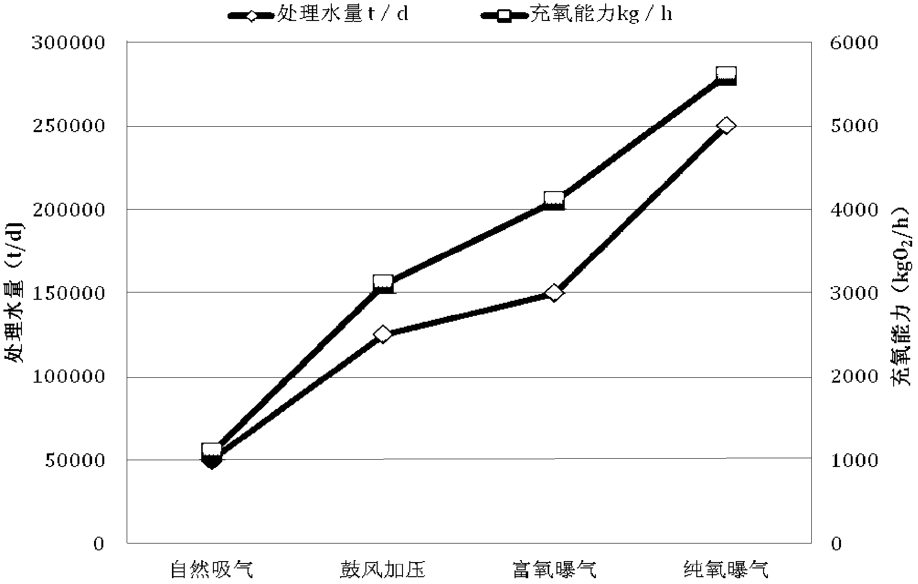
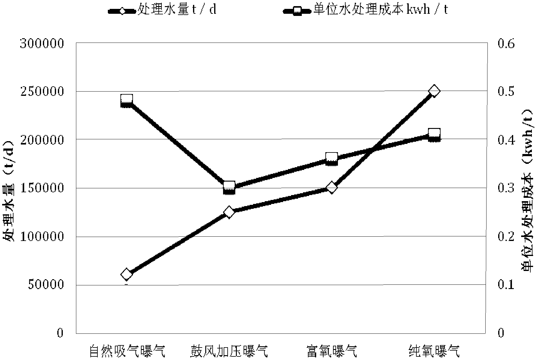
The invention discloses an aeration system which comprises gas sources, a gas feed control device, a power water pump, an ejector and a synergistic nozzle; the gas sources comprise an air source and an oxygen source, the gas feed control device controls selection of a gas source and the quantity of gas flow, and the power water pump allows water pumped from an aeration tank to form pressure fluid and supplies the pressure fluid to the ejector; the synergistic nozzle is connected with an output terminal of the ejector through a pipeline and sprays water-vapor mixed liquor output by the output terminal of the ejector below the water surface of the aeration tank. According to the invention, the aeration system uses the gas feed control device to control selection of a gas source and the quantity of gas flow according to load of water treatment, which enables the aeration system to have the three functions of pure oxygen aeration, oxygen-rich aeration and air aeration; therefore, air aeration can be used under the condition of a normal water volume, pure oxygen or oxygen-rich aeration can be used under the conditions that load greatly fluctuates and sewage treatment scale needs to be greatly improved, and on the premise that no reconstruction or enlargement is needed, sewage treatment capability is enhanced and sewage treatment cost per unit is reduced.

Description

technical field [0001] The invention relates to water treatment equipment, in particular to an aeration system. Background technique [0002] Sewage treatment is the main work of water pollution prevention and rational development and utilization of water resources. In the process of sewage treatment, aerobic biochemical method is a more perfect process after physical treatment. The main treatment cost of aerobic biochemical method is Aeration, to control the aeration cost and reduce the aeration cost per unit of sewage treatment, is the key to reducing the cost of aerobic biochemical treatment. [0003] Aerobic microorganisms need a large amount of oxygen when oxidizing organic matter. Usually, the supply of oxygen is the aeration process of forcibly dissolving the oxygen in the air into the sewage. In addition to the above-mentioned oxygen supply, the aeration process also plays a stirring role to make the active sewage The mud remains suspended in the sewage and is fully...

Claims


Application Information

Patent Timeline
IPC IPC(8): C02F7/00C02F3/12C02F3/26
CPCY02W10/10
Inventor 杨忠明
Owner 成都绿水科技有限公司
Learn More