
Electric bus battery quick-change robot system and quick-change method

A robot system and electric bus technology, applied in electric vehicles, electric power devices, charging stations, etc., can solve the problems of increasing the working space of the battery replacement system, the large space occupied by the replacement equipment, and the long time to replace the power battery. The effect of small displacement, safe replacement and quick replacement

Active Publication Date: 2012-06-13
STATE GRID INTELLIGENCE TECH CO LTD
View PDF7 Cites 46 Cited by
  • Summary
  • Abstract
  • Description
  • Claims
  • Application Information

AI Technical Summary

Problems solved by technology

[0007] Existing quick-change electric manipulators for electric vehicle batteries, such as patent 200820078476.7 "a positioning device for vehicle-mounted battery replacement system" and patent 200410090796.0 "an electric bus system", etc., although the vehicle-mounted power battery is disclosed as the power source However, there are also some problems in the application of the described device, such as: the process of replacing the battery requires multiple positioning, and the time for replacing the power battery is long; the space occupied by the replacement equipment is large, which is not conducive to the layout of the site; the battery During the replacement process, the battery must be rotated 180° to increase the working space of the battery replacement system, etc.

Method used

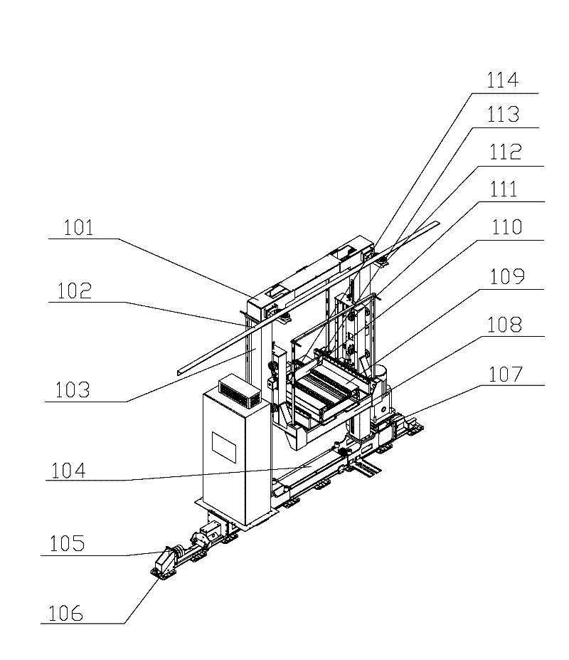

Image

  • Electric bus battery quick-change robot system and quick-change method
  • Electric bus battery quick-change robot system and quick-change method
  • Electric bus battery quick-change robot system and quick-change method

Examples


Embodiment Construction

[0039] The present invention will be further described below in conjunction with the accompanying drawings and embodiments.

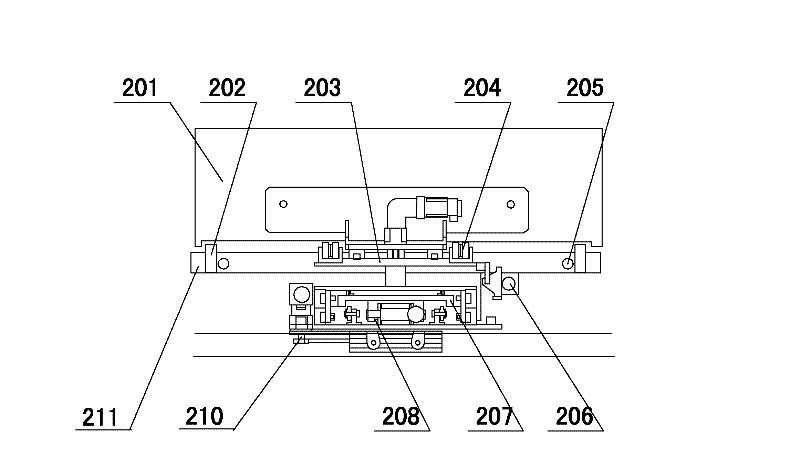
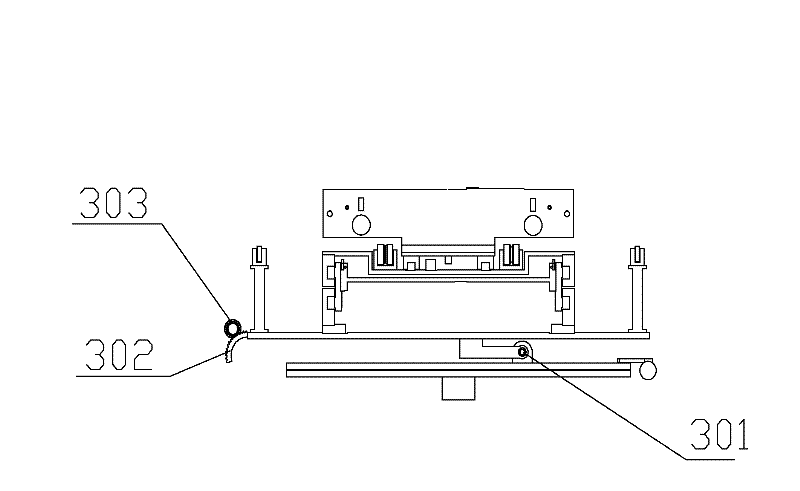
[0040] figure 1 , figure 2 The figure shows the schematic diagram of the rear view structure of the quick-change robot and the loading platform unit of the present invention. In the figure, the mechanical part of the system is provided with a horizontal moving unit 107, a loading platform unit and a load-bearing unit, so that the three-coordinate main structure of the system is established. The horizontal moving unit 1077 includes rollers and follower rollers with rims on both sides, and a ground rail 105 connected to the lower beam 104 of the load-bearing unit. The end of the ground rail 105 is provided with a limit bumper 106, and the rollers and The follower roller is connected with the motor reducer, and the motor reducer is connected with the lower beam 104 of the load-bearing unit. The load-bearing unit is arranged on the top of the horizontal ...


PUM


Abstract

The invention discloses an electric bus battery quick-change robot system and a quick-change method. The electric bus battery quick-change robot system comprises a robot body, the robot body consists of a mechanical portion and an electric control system, wherein the mechanical portion comprises a horizontal moving unit, a carrying platform unit and a bearing unit which are arranged on an X rectangular coordinate direction, a Y rectangular coordinate direction and a Z rectangular coordinate direction, the carrying platform unit comprises a carrying platform and a battery driving mechanism disposed on the carrying platform, and a battery pushing mechanism is arranged on the battery driving mechanism; and the electric control portion comprises a data acquisition device, a power driving mechanism and an I / O (input / output) module, and the data acquisition device is connected with a master control computer system. When the quick-change robot is applied, positioning precision in a quick-change process is high, relative displacement is low, positions are accurate, and power batteries of various electric buses can be quickly changed by the aid of the electric bus battery quick-change robot system.

Description

technical field [0001] The invention relates to a battery quick-changing system and a quick-changing method between an electric vehicle and a battery transfer station, in particular to a battery quick-changing robot system and a quick-changing method for an electric bus. Background technique [0002] With the continuous increase of the dual pressure of resources and the environment, in order to alleviate the shortage of oil resources and reduce the pollution of automobile fuel to the environment, the development of new energy vehicles has become the direction of the future development of the automobile industry. At present, "low-emission" vehicles (mainly referring to hybrid vehicles) have entered the stage of large-scale industrialization, and the cumulative global sales volume has exceeded 1 million. The time for mass production of "zero-emission" vehicles (mainly referring to pure electric vehicles) has passed Advance to 2015, 10 to 15 years earlier than originally expect...

Claims


Application Information

Patent Timeline
IPC IPC(8): B60S5/06
CPCB60L53/80Y02T10/70Y02T10/7072
Inventor 厉秉强王同斌谭林赵金龙高先进
Owner STATE GRID INTELLIGENCE TECH CO LTD
Learn More