
Grid shearing fixation device for lead-acid storage battery

A technology for fixing devices and grids, which is applied in the direction of shearing devices, attachments of shearing machines, metal processing equipment, etc., and can solve the problems that restrict the popularization and application of new cutting knives and cannot work normally.

Active Publication Date: 2013-12-04
JIANGSU SANHUAN IND HLDG CO LTD
View PDF6 Cites 0 Cited by
  • Summary
  • Abstract
  • Description
  • Claims
  • Application Information

AI Technical Summary

Problems solved by technology

However, when this new cutter works, the ribs on the grid must be accurately fixed one by one, otherwise it will not work normally, and there is no corresponding fixing device in the past that can meet this requirement, thus restricting this new cutter. The promotion and application of knives

Method used


Image

  • Grid shearing fixation device for lead-acid storage battery
  • Grid shearing fixation device for lead-acid storage battery
  • Grid shearing fixation device for lead-acid storage battery

Examples


Embodiment Construction

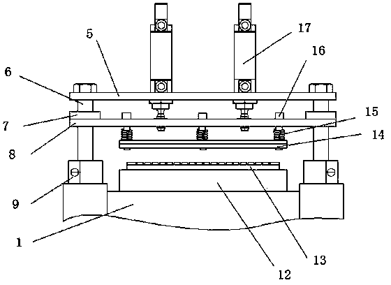
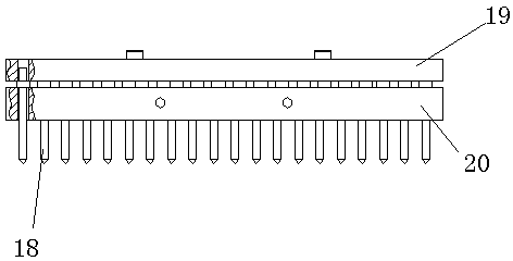
[0023] Such as figure 1 As shown, the grid shearing and fixing device A in the present invention is arranged in front of the shearing device 1, and is positioned on the movement path of the grid, as figure 2 As shown, it includes a fixed seat and a pressing plate fixing mechanism and a tendon carding mechanism arranged on the fixed seat.

[0024] Such as Figure 2-5 As shown, the fixed seat includes a base 9, a fixed seat plate 5 and a carding mechanism installation plate 22, and the base 9 and the fixed seat plate 5 are connected by two guide rods 6 in the first guide mechanism. The pressing plate fixing mechanism comprises a lower fixing plate 13, an upper fixing plate 14, a pressing plate driving mechanism and a first guiding mechanism. The first guide mechanism includes two guide rods 6 and a sliding seat which is arranged on the guide rods 6 and can reciprocate along the guide rods 6 . The lower ends of two guide rods 6 are fixed on the frame 1 of the transmission mec...


PUM


Abstract

The invention discloses a grid shearing fixation device for a lead-acid storage battery. The device comprises a fixed base as well as a pressing plate fixation mechanism and a grid rib combing mechanism which are arranged on the fixed base, wherein the pressing plate fixation mechanism comprises a lower fixed plate, an upper fixed plate and a pressing plate driving mechanism, one of the upper fixed plate and the lower fixed plate is arranged on a first guiding mechanism which is arranged on the fixed base, and the upper fixed plate and the lower fixed plate are driven by the pressing plate driving mechanism and are closed under the guiding of the first guiding mechanism so as to clamp and fix a grid positioned between the upper fixed plate and the lower fixed plate; and the grid rib combing mechanism comprises an insertion assembly, a second guiding mechanism and an insertion driving mechanism, comb teeth which correspond to gaps between adjacent ribs on the grid one by one are distributed on the insertion assembly, the second guiding mechanism and the insertion driving mechanism are fixed on the fixed base, and the insertion assembly is arranged on the second guiding mechanism and is driven by the insertion driving mechanism to move along the second guiding mechanism, so that the comb teeth on the insertion assembly are inserted into the gaps between the adjacent ribs so as to limit the horizontal positions of the ribs of the grid.

Description

technical field [0001] The invention relates to a device for securing a grid during shearing operations. Background technique [0002] After the lead-acid battery grid is die-cast by a die-casting machine, it needs to go through processes such as cutting and casing before it can be applied to the battery. [0003] Earlier, the shearing process of the grid was completed by workers manually operating the cutter. Due to the high labor intensity, low production efficiency and low cutting quality of this operation method, people later designed a special grid shearing device to complete the process. Shear work of the grid. [0004] The cutting knife used in the previous grid shearing device is the same as that used in manual operation. The fracture of the sheared grid rib is plane, and this plane fracture often punctures the casing, and when shearing The ribs on the grid are easily distorted and deformed, which makes the scrap rate of the grid very high. For this reason, people ...

Claims


Application Information

Patent Timeline
Patent Type & Authority Patents(China)
IPC IPC(8): B23D33/02
Inventor 汪群华沈小庚
Owner JIANGSU SANHUAN IND HLDG CO LTD
Learn More