
Minimum triggering angle running test method for high-voltage direct current power transmission converter valve

A high-voltage direct current transmission and operation test technology, applied in the field of power electronics, can solve problems such as poor compatibility, and achieve good generality and good method versatility.

Active Publication Date: 2012-06-06
CHINA ELECTRIC POWER RES INST +1
View PDF7 Cites 2 Cited by
  • Summary
  • Abstract
  • Description
  • Claims
  • Application Information

AI Technical Summary

Problems solved by technology

[0003] The current synthetic test circuit realizes the minimum firing angle operation test. The basic principle is to use two power supplies to respectively provide the high voltage during the blocking period and the high current during the opening period of the test product. The test circuit can complete the minimum firing angle operation of the converter valve. Experimental, but poor compatibility
[0004] For example, in the application number 200910243596.7 disclosed by the applicant, a DC converter valve minimum trigger angle operation test method is used to achieve the required minimum trigger voltage through the strategy of auxiliary valve pressure division, and to meet the energy acquisition of the test product by adding an oscillation process. , the test circuit can well complete the minimum trigger angle, minimum cut-off angle and other running tests, but there is a contradiction between the low trigger voltage and the high test voltage, the opening time of the test valve cannot be adjusted, and the compatibility is poor

Method used


Image

  • Minimum triggering angle running test method for high-voltage direct current power transmission converter valve
  • Minimum triggering angle running test method for high-voltage direct current power transmission converter valve
  • Minimum triggering angle running test method for high-voltage direct current power transmission converter valve

Examples


Embodiment Construction

[0022] The present invention will be further described in detail below in conjunction with the accompanying drawings and specific embodiments.

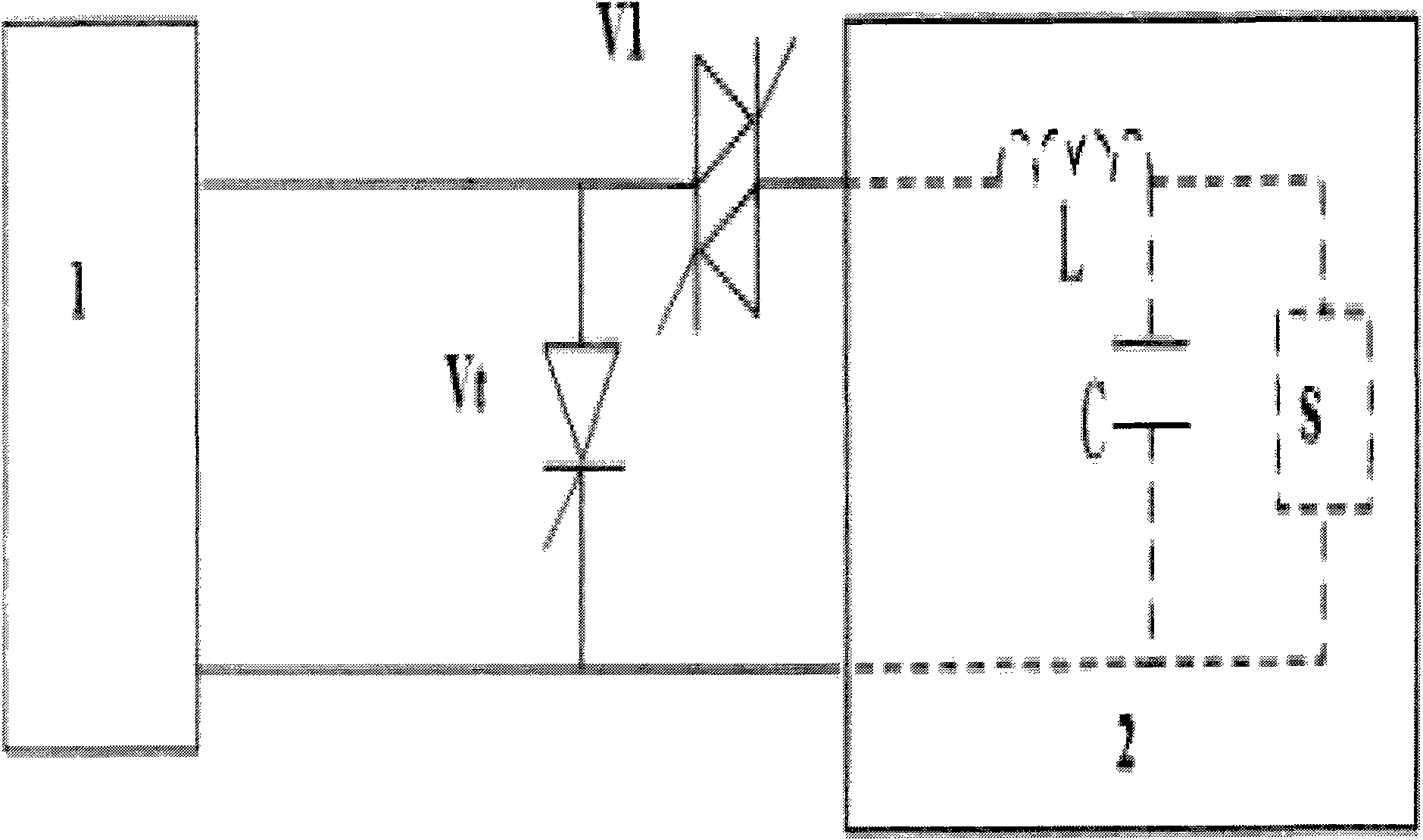
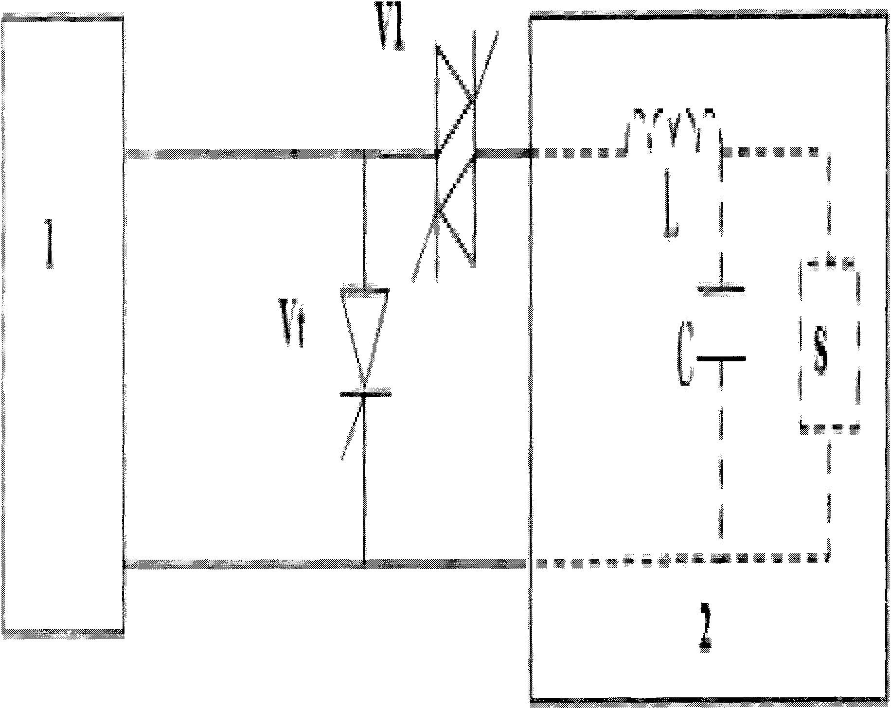
[0023] figure 1 It is a schematic diagram of the minimum trigger angle operation test device for HVDC converter valves. The device includes low-voltage high-current DC power source 1, high-voltage small current source 2, auxiliary valve V1 and test valve Vt, among which low-voltage high-current DC source 1, test Sample valve Vt and high-voltage small current source 2 are connected in parallel in turn; one end of auxiliary valve V1 is connected to low-voltage high-current DC source 1, test valve Vt and high-voltage small current source 2, and the other end of auxiliary valve V1 is connected to the resonance in high-voltage small current source 2. Inductor L; high voltage and small current source 2 includes charging power source S, resonant capacitor C and resonant inductor L, charging power source S and resonant capacitor C are connect...


PUM


Abstract

The invention provides a minimum triggering angle running test method for a high-voltage direct current power transmission converter valve. According to the method, switch-on voltage of a test sample valve Vt is flexibly selected by selecting a triggering moment of an auxiliary valve V1 during charging of a resonant capacitor C according to different engineering requirements, and is adjustable continuously; and therefore, the contradiction between low triggering voltage and high test voltage is solved, and the low triggering voltage and the high test voltage are not interfered with each other. The method is suitable for different test sample valves, and is high in generality.

Description

technical field [0001] The invention relates to an operation test method in the field of power electronics, in particular to a minimum trigger angle operation test method for a high-voltage direct current transmission converter valve. Background technique [0002] At present, HVDC transmission technology is developing rapidly and widely used in power systems. Compared with traditional AC transmission technology, an important feature of HVDC transmission technology is that it can control power transmission in a large range, continuously and quickly, because the DC transmission converter valve can be quickly opened within a wide range of opening angles. When the system voltage drops and the opening angle is extremely small, the opening voltage of the converter valve is extremely small, which is unfavorable for the reliable opening of the converter valve. The converter valve should be considered in the design and needs to be verified and improved by corresponding test methods ...

Claims


Application Information

Patent Timeline
IPC IPC(8): G01R31/327
Inventor 高冲杨俊查鲲鹏
Owner CHINA ELECTRIC POWER RES INST
Learn More