Unfurled metal sealing ball valve

A metal-sealed, spread-out technology, applied to valve devices, cocks including cut-off devices, engine components, etc., can solve the problems of long guide groove travel, affecting valve quality, and easy mutual damage, etc., and achieves low manufacturing costs. Easy to process and good applicability

Inactive Publication Date: 2012-06-06
ZHEJIANG ZHENGHUA VALVE FACTORY
View PDF11 Cites 7 Cited by
  • Summary
  • Abstract
  • Description
  • Claims
  • Application Information

AI Technical Summary

Problems solved by technology

[0013] The upper lifting mechanism follows the single-track opening and closing structure of the screw in the track ball valve of the American track valve company. This structure has been used in ball valves and plug valves in my country's valve industry since the introduction of technology. The advantages are obvious, but there are shortcomings. The required stroke route of the guide groove is long, and the jamming phenomenon occurs when the guide pin forms a transition point from the straight notch to the curved notch, and the linear contact surface between the cylindrical surface of the guide pin and the guide groove of the valve stem is easy to interact with each other. Damage, affecting the overall quality of the valve

Method used


Image

  • Unfurled metal sealing ball valve
  • Unfurled metal sealing ball valve
  • Unfurled metal sealing ball valve

Examples


Embodiment Construction

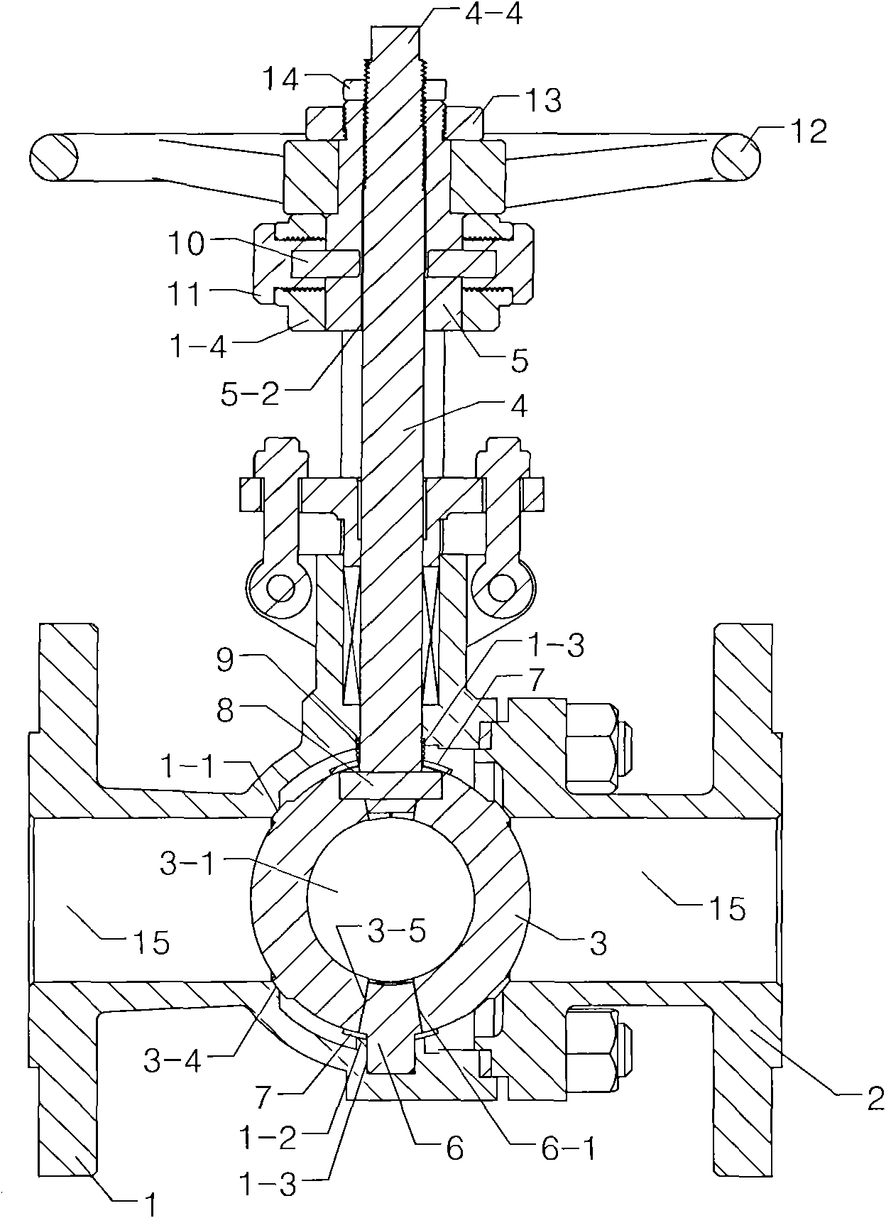
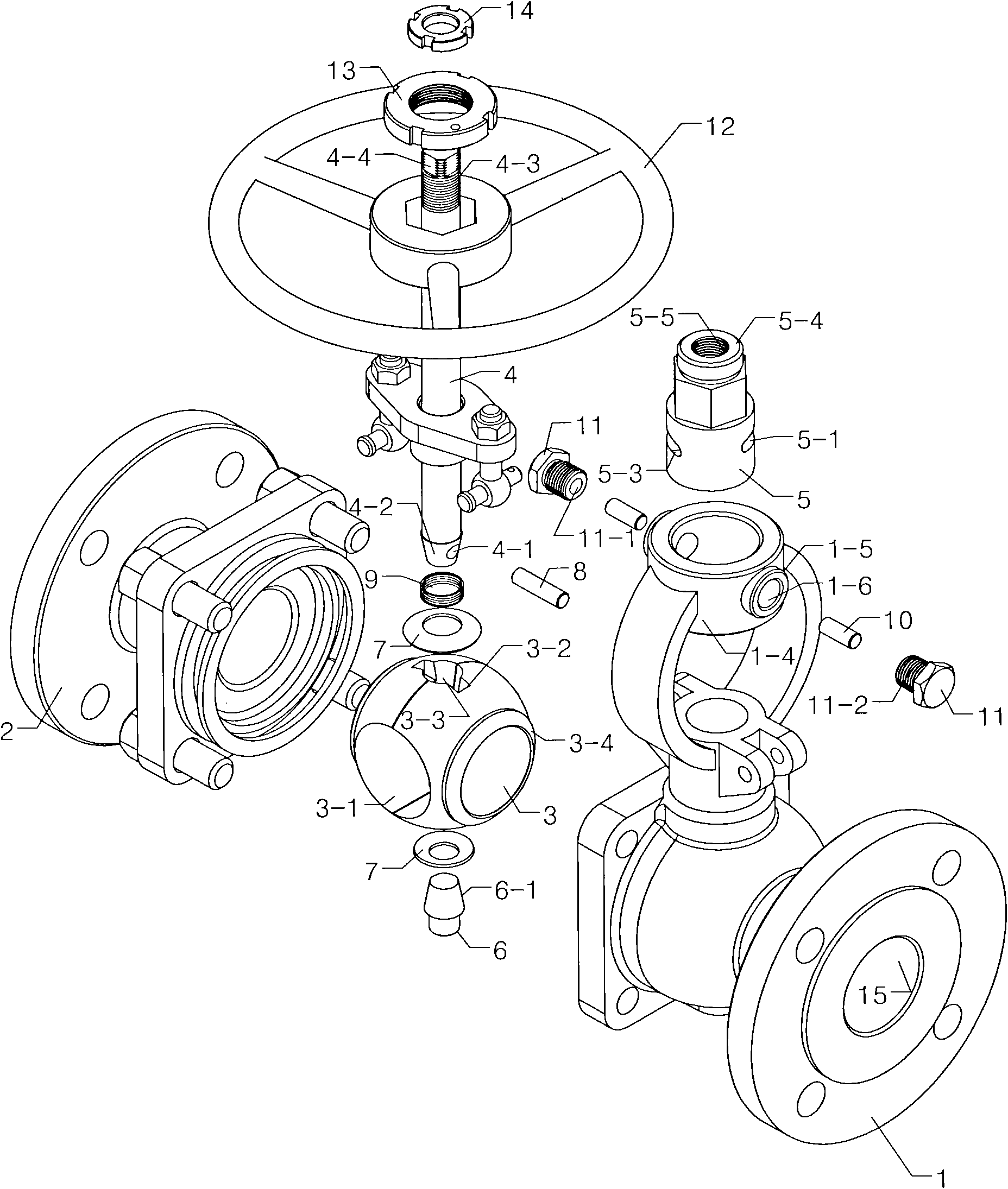
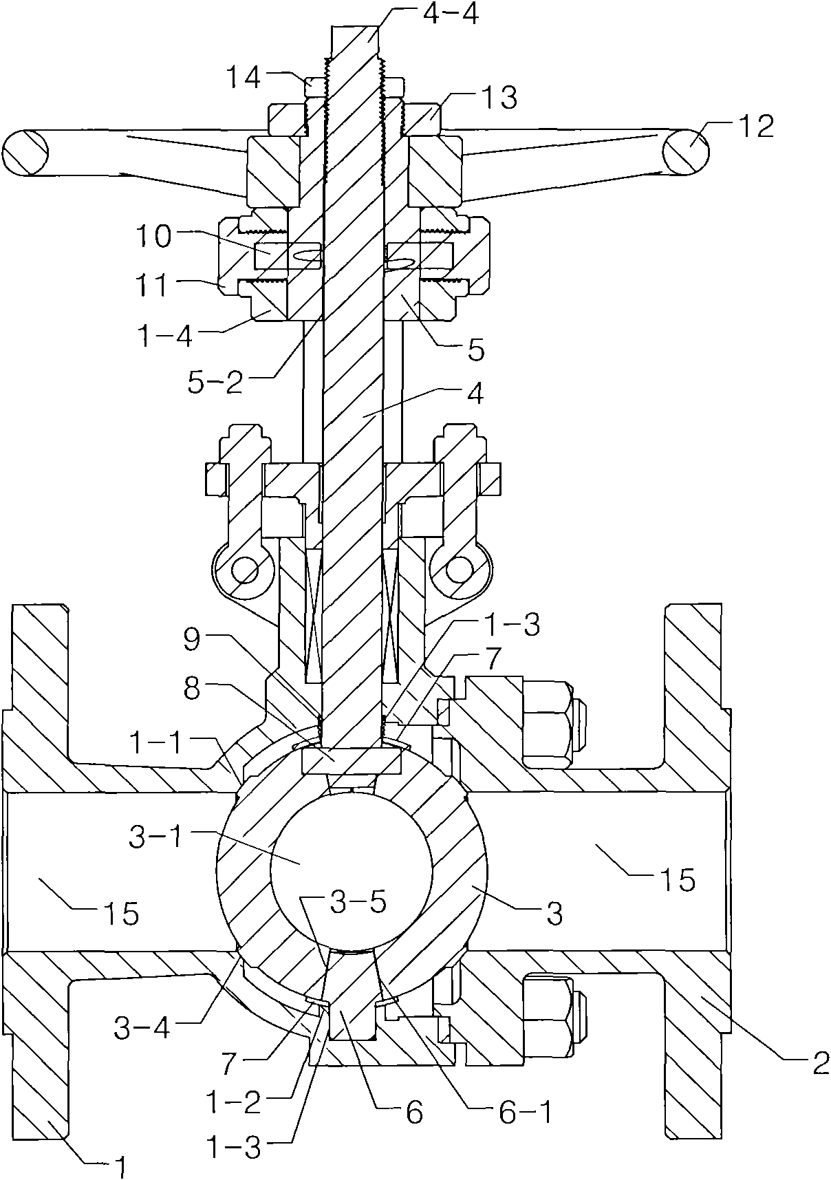
[0038] According to the embodiment of the present invention, the ball valve mainly includes a valve body (1) and a connecting body (2), a channel (15) for transmitting liquid medium is provided in the inner cavity of the valve, and a channel (15) is provided between the opening and closing positions of the valve in the channel. A sphere (3) that selectively rotates to control liquid flow. The sphere (3) is a two-piece structure that is symmetrical to each other. The sealing surface of the raised annular flange (1-1) (commonly called the valve seat) so that the seal (3-4) of the mating ball (3) is pressed against it.

[0039]In order to ensure that the sphere (3) has a certain positional relationship while moving in the valve body (1), a round table (1-2) is set at the lower end of the valve body (1), and the vertical center of the sphere (3) has a container The cone (4-2) at the end of the valve stem (4) and the cone plug (6) match the same holes (3-3) and (3-5), and the two c...


PUM


Abstract

The invention provides an unfurled metal sealing ball valve. A ball body is in a two-piece structure. A circular conical surface for containing a valve rod and holes in consistent fit with a tapered plug are arranged at the center of the ball body. Two tapered holes extend along a flow channel direction in the same direction and butterfly-shaped springs are arranged at upper and lower ends of the center of the ball body; the upper end of the ball body is provided with a cross straight notch for containing a pin and the pin is fixedly connected with the hole on the circular conical surface of the valve rod; and spiral springs are contacted with the butterfly-shaped springs through one end of the valve rod and the other ends of the valve rod is placed into a middle stage hole of a valve body. The top end of the valve body is provided with an annular boss and a through hole is matched with a transposition sleeve; a cylinder body which stretches out of the outer side is arranged at the outer edge and the inner part of the cylinder body is provided with a thread which is engaged with a screw plug. Annular notches are symmetrically designed on the circumference of the part which is close to the lower part in the middle of the transposition sleeve at the 90-degree direction; a straight line section is arranged in a range of about 70-degree direction and a downward inclined line section is arranged in a range of about 20-degree direction; the inclined degree ratio of the inclined line section to the straight line section is in a range of 3-5 degrees; and the inner part of the upper end of the transposition sleeve is a thread connected with the thread on the valve rod.

Description

technical field [0001] The invention belongs to a ball valve, and in particular relates to the design of a lifting valve stem and a sealing pair of a stretching ball. Background technique [0002] The ball valve has many advantages, mainly because the valve core is a ball with a cavity, and the ball is controlled by the valve stem to rotate 90° to open or close the valve. Due to the small fluid resistance, the switch is fast and convenient, with long life and high reliability. Has been widely used. [0003] The sealing forms of the existing ball valves are various, and they can be summarized into the following two types. [0004] 1. Ordinary floating ball valve with soft surface seal [0005] The characteristics of ordinary seated ball valves are: under the action of pretightening force or fluid pressure, the seat material is mostly special plastics, such as PEEKP (polyetheretherketone) PTFE (polytetrafluorohexene), which are relatively harder and more rigid. It is made o...

Claims


Application Information

Patent Timeline
Patent Type & Authority Applications(China)
IPC IPC(8): F16K5/06
Inventor 戴学祥陈贤良王爵义王燊王克志王靖胜
Owner ZHEJIANG ZHENGHUA VALVE FACTORY
Why Eureka
Try Eureka