
Water cooling tower

A water cooling tower and water potential technology, applied in the direction of water shower coolers, engine components, machines/engines, etc., can solve problems such as limitations and neglect of potential energy, and achieve the effect of reducing cost and tower height

Inactive Publication Date: 2012-05-30
DALIAN CHUANGDA TECH TRADE MARKET
View PDF0 Cites 6 Cited by
  • Summary
  • Abstract
  • Description
  • Claims
  • Application Information

AI Technical Summary

Problems solved by technology

[0005] That is to say: the traditional cooling tower technology consumes money or energy, and the existing new technology has limitations; the traditional cooling concept ignores the potential energy of the hot water entering the cooling tower, and the existing new technology only uses a part of the potential energy of the hot water , and did not fundamentally change the traditional cooling concept

Method used


Image

  • Water cooling tower
  • Water cooling tower
  • Water cooling tower

Examples


Embodiment Construction

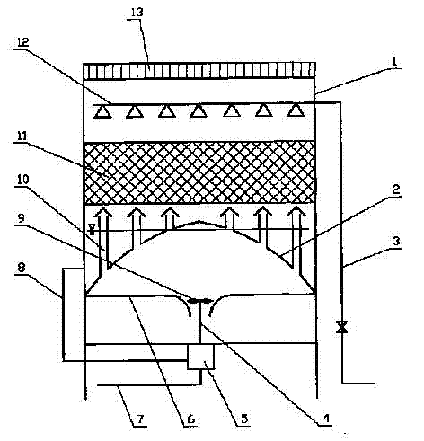
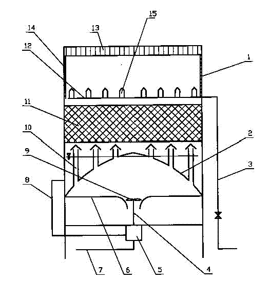
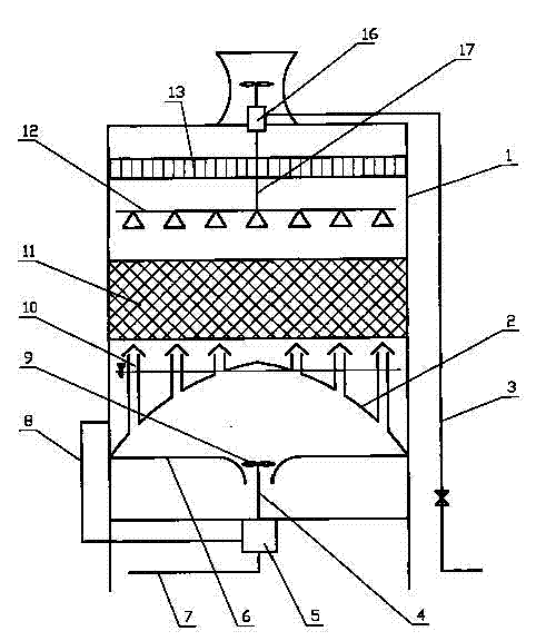
[0014] With reference to Fig. 1, the water energy self-cooling cooling water tower that the present invention provides, the upper end side of cooling water tower 1 is connected with the hot water inlet pipe 3 to be treated, and water inlet pipe 3 connects the water distribution pipe 12 of cooling water tower 1 inside, and above water distribution pipe 12 has Water eliminator 13, under the water distribution pipe 12 there is a water spraying packing layer 11, under the packing layer 11 there is an air-cooled distribution plate 2, the distribution plate 2 is equipped with a cap-shaped air distribution pipe 10, and the outlet pipe 8 is connected to a water outlet that uses the potential energy of the water outlet to drive , thereby driving the water energy machine 5 of the blower 9 to work, and the outside of the blower 9 has an air distribution enclosure 6. The water energy machine 5 is installed in the center of the bottom of the cooling tower 1, and its power output shaft 4 ext...


PUM


Abstract

A water cooling tower is equipped with a water power machine which is connected with a water outlet of the water cooling tower, and is driven by water potential energy so as to drive a blower to work. The water power machine is mounted at the center of the bottom of the water cooling tower, and has a power take-off shaft which extends upwards into the inside of the water cooling tower and is connected with the blower. The invention makes full use of the potential energy of hot water itself to cool the hot water, and establishes a brand new water cooling tower mode in which the operation of the water cooling tower does not consume energy any more; both the tower height and the cost are reduced; no construction of natural-ventilation hyperbolic cooling towers with high cost is necessary.

Description

[0001] technical field [0002] The invention relates to an industrial and civil cooling tower, in particular to a cooling water cooling tower. Background technique [0003] Among the existing industrial and civil cooling towers, although the natural ventilation cooling tower does not consume additional energy during operation, its tower body is tall and requires a large one-time investment; while other cooling towers with relatively low one-time investment all use mechanical cooling towers. Force ventilation cooling technology, that is, an exhaust fan is installed in the air duct of the cooling tower, and the power is provided by the motor outside the air duct. That is to say, the traditional cooling concept believes that turning hot water into cold water through cooling towers can either be solved with a large one-time investment, or it can be achieved by consuming power during daily operation. [0004] At present, most of the new technologies for energy saving of...

Claims


Application Information

Patent Timeline
IPC IPC(8): F28C1/00F03B13/00
Inventor 杜冲
Owner DALIAN CHUANGDA TECH TRADE MARKET
Learn More