Exhaust gas recirculation valve
A technology of exhaust gas circulation and valve seat, which is applied in the field of valve and valve seat shape, can solve the problems of valve core switch influence, sealing part burden, leakage increase, etc., achieve low-cost manufacturing, improve bite resistance, and simplify valve seat shape Effect
- Summary
- Abstract
- Description
- Claims
- Application Information
AI Technical Summary
Problems solved by technology
Method used
Image
Examples
Embodiment approach 1
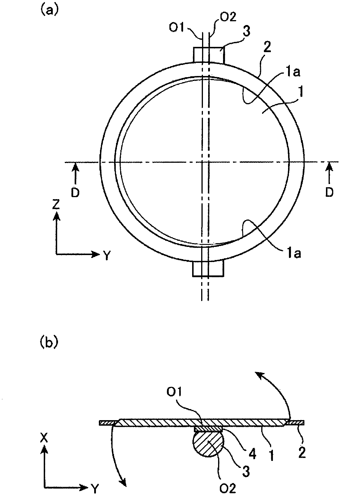
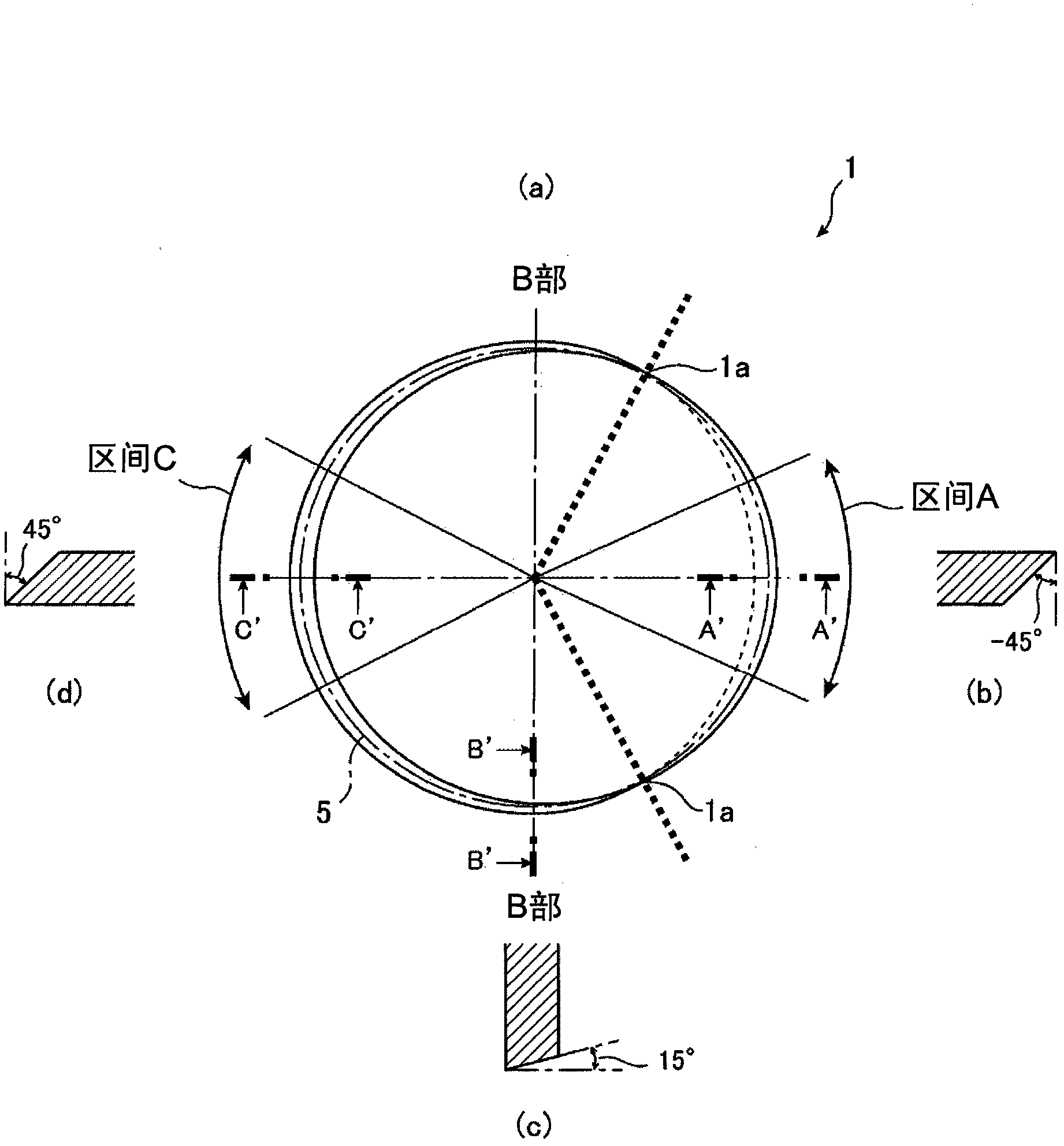
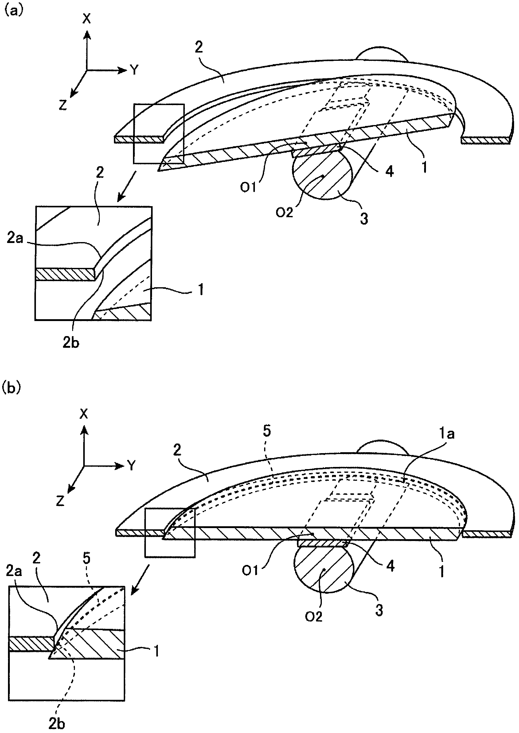
[0022] figure 1 (a) is a plan view of the exhaust gas recirculation valve according to Embodiment 1 of the present invention, figure 1 (b) is along figure 1 (a) Cross-sectional view taken along line DD. figure 2 (a) is a plan view showing the shape of the valve 1, in figure 2 (b), figure 2 (c), figure 2 (d) shows a cross-sectional view cut along line A'A', line B'B', and line C'C'. image 3 (a) is along figure 1 (a) The cross-sectional perspective view of the open valve state cut by the DD line, image 3 (b) is a cross-sectional perspective view in a valve closed state.
[0023] The exhaust gas recirculation valve includes: a substantially circular valve 1 ; a valve seat 2 having a perfectly circular opening; a shaft 3 for rotating the valve 1 ; and a plate 4 provided between the valve 1 and the shaft 3 . A straight line passing through the center of the perfectly circular valve seat 2 is defined as a center line O1, and a rotation center axis of the shaft 3 when t...
Embodiment approach 2
[0032] Figure 4 shows the structure of the exhaust gas recirculation valve of Embodiment 2, Figure 4 (a) is a plan view, Figure 4 (b) is along Figure 4 (a) The sectional view cut by the EE line, Figure 4 (c) is along Figure 4(a) Cross-sectional view cut along the center line O1. The exhaust gas recirculation valve shown in Embodiment 1 above has a biaxial eccentric structure, but in Embodiment 2, the exhaust gas recirculation valve has a uniaxial eccentric structure. That is, the rotation axis O2 of the shaft 3 is uniaxially eccentric with respect to the center line O1 of the valve seat 2 from the center of the valve toward the long base side of the trapezoid. The valve 1 is bilaterally symmetrical with respect to the rotation axis O2 of the shaft 3 in the closed state, so there is no pressure difference between the left and right pressures of the exhaust gas received by the valve 1 in the closed state. Therefore, the valve opening force due to the pressure differe...
Embodiment approach 3
[0037] Figure 5 It is a plan view showing the structure of the exhaust gas recirculation valve of Embodiment 3.
[0038] In the exhaust gas recirculation valve of Embodiment 1 described above, in order to form a biaxial eccentric structure, the rotation axis O2 of the shaft 3 is shifted in the Y direction with respect to the center line O1 of the valve seat 2 . Therefore, the torque generated by the valve 1 on the left and right surfaces relative to the shaft O2 of the shaft 3 is slightly different. force. Therefore, in Embodiment 3, if Figure 5 As shown, in addition to the biaxial eccentric structure, it can also be configured as a balanced valve structure.
[0039] exist Figure 5 Among them, the structure is as follows: by reducing the area indicated by the oblique lines of the valve 1 and the valve seat 2 respectively, and making the torque generated on the left and right surfaces of the valve 1 centered on the rotation axis O2 of the shaft 3 be the same, it is possi...
PUM
 Abstract
Description
Claims
Application Information
 - R&D
- Intellectual Property
- Life Sciences
- Materials
- Tech Scout
- Unparalleled Data Quality
- Higher Quality Content
- 60% Fewer Hallucinations
Browse by: Latest US Patents, China's latest patents, Technical Efficacy Thesaurus, Application Domain, Technology Topic, Popular Technical Reports.
© 2025 PatSnap. All rights reserved.Legal|Privacy policy|Modern Slavery Act Transparency Statement|Sitemap|About US| Contact US: help@patsnap.com


