
Method for testing linewidth uniformity

A test method and uniformity technology, applied in the field of line width uniformity test, can solve problems such as the inability to truly reflect the performance of the lithography machine lens

Active Publication Date: 2013-11-06
CSMC TECH FAB2 CO LTD
View PDF5 Cites 1 Cited by
  • Summary
  • Abstract
  • Description
  • Claims
  • Application Information

AI Technical Summary

Problems solved by technology

However, due to the influence of the lithography plate manufacturing process, the line width of the repeated test patterns in each area on the final lithography plate is inconsistent, so the measured line width uniformity will be affected by the error of the lithography plate making, that is to say, it will Affected by the joint effect of lithography plate making and lithography machine lens, it cannot truly reflect the performance of lithography machine lens

Method used


Image

  • Method for testing linewidth uniformity
  • Method for testing linewidth uniformity
  • Method for testing linewidth uniformity

Examples


Embodiment Construction

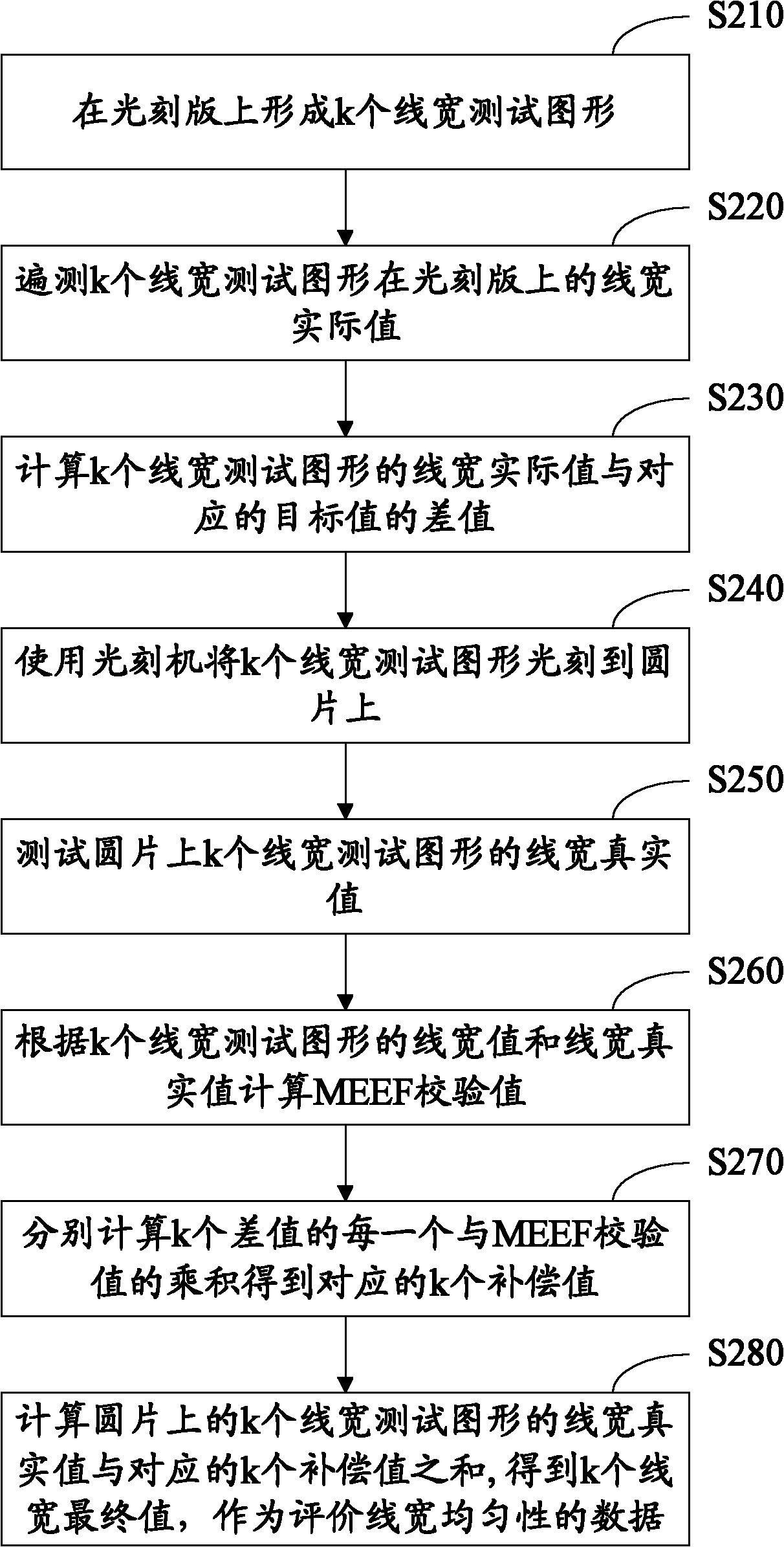
[0021] The present invention utilizes the principle of MEEF (mask error enhancement factor, lithographic plate error enhancement factor) to obtain a test method for line width uniformity with simplified test steps. figure 2 It is a flow chart of a test method for line width uniformity in an embodiment, comprising the following steps:

[0022] S210, forming k line width test patterns on the photolithography plate.

[0023] The design value of the uniformly distributed line width on the photolithography plate is the target value A 1 、A 2 ,...,A k k line width test patterns, k is a natural number.

[0024] In this embodiment, each line width test pattern includes two line width figures, and these two line width figures are inverse patterns (that is, the translucent and opaque parts are just opposite), so as to meet different types of tests. Requirements, that is, to test the bar structure and to test the spacing between each bar structure. In a preferred embodiment, each li...


PUM


Abstract

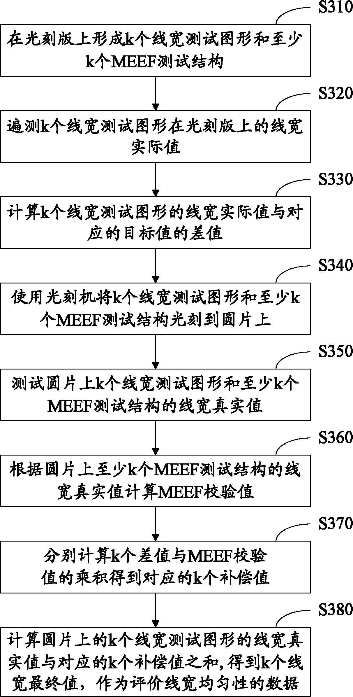
The invention relates a method for testing linewidth uniformity. The method comprises the following steps of 1, preparing k linewidth testing figures of which desired values are linewidth design values on a lithographic plate, 2, testing linewidth actual values of all the k linewidth testing figures on the lithographic plate, 3, calculating k differences between the linewidth actual values of the k linewidth testing figures and the corresponding desired values, 4, carrying out photoetching of the k linewidth testing figures on a disk, 5, testing linewidth real values of the k linewidth testing figures on the disk, 6, calculating mask error enhancement factor (MEEF) verification values according to the desired values or the linewidth actual values as linewidth values of the k linewidth testing figures, and the linewidth real values, 7, respectively calculating the product of the k differences and the MEEF verification values so that k corresponding compensation values are obtained, and 8, calculating the sum of the linewidth real values of the k linewidth testing figures and the k corresponding compensation values so that k linewidth final values are obtained, wherein the k linewidth final values are utilized as linewidth uniformity evaluation data. The method provided by the invention has the advantage that plate making error compensation values are obtained by MEEF verification value calculation so that a plate making error is avoided.

Description

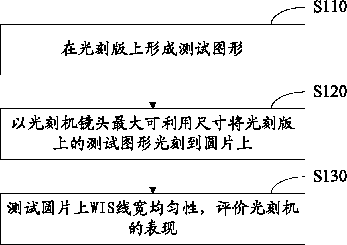
【Technical field】 [0001] The invention relates to a semiconductor process, in particular to a test method for line width uniformity used for performance evaluation of a lithography machine lens. 【Background technique】 [0002] The single imaging area on the wafer after the photolithography pattern is exposed through the lens of the lithography machine is called a shot. The uniformity of line width in each shot on the wafer is an important parameter of the lithography process, especially the shot size is lithography The uniformity of line width at the maximum available range of the machine lens is a key indicator for evaluating lithography machines. [0003] The traditional evaluation method is to repeatedly place some line width test patterns on the photolithography plate, test the line width after exposure on the wafer, and obtain the line width uniformity within shot (within shot, WIS). figure 1 It is a flow chart of the traditional test method of line width uniformity. ...

Claims


Application Information

Patent Timeline
Patent Type & Authority Patents(China)
IPC IPC(8): G03F7/20G01M11/02
Inventor 黄玮段天利邹永祥胡骏张辰明刘志成
Owner CSMC TECH FAB2 CO LTD
Learn More