
Lens module capable of switching focuses

A lens module and focus technology, applied in installation, optics, instruments, etc., can solve the problems of high cost, small magnetic force, and large volume, and achieve the effects of simplified parts, easy manufacturing and assembly, and small volume

Inactive Publication Date: 2012-05-23
ASIA OPTICAL CO INC
View PDF5 Cites 4 Cited by
  • Summary
  • Abstract
  • Description
  • Claims
  • Application Information

AI Technical Summary

Problems solved by technology

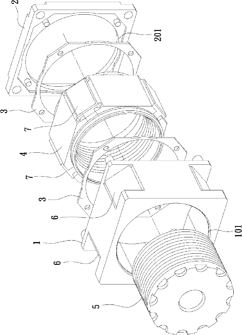
[0004] 1. These coil components 6 are printed coils, which can generate small magnetic force, so four must be provided along the circumferential direction of the frame 1, and these magnetic components 7 are also correspondingly arranged on the outer peripheral surface of the bearing seat 4 , so that the overall components of the lens device are many, and the volume is large, which does not meet the needs of miniaturization
[0005] 2. When the carrying base 4 drives the lens 5 to move to complete the zoom action, it is necessary to use these guide slopes 101, 201 to provide the opposite side edges of the bearing base 4 to collide and guide, so as to achieve alignment and maintain alignment. When the tolerance must be strict, the cost will be higher

Method used


Image

  • Lens module capable of switching focuses
  • Lens module capable of switching focuses
  • Lens module capable of switching focuses

Examples


Embodiment Construction

[0016] The aforementioned and other technical contents, features and effects of the present invention will be clearly presented in the following detailed description of a preferred embodiment with accompanying drawings.

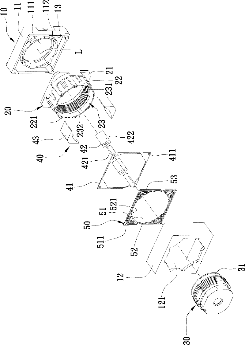
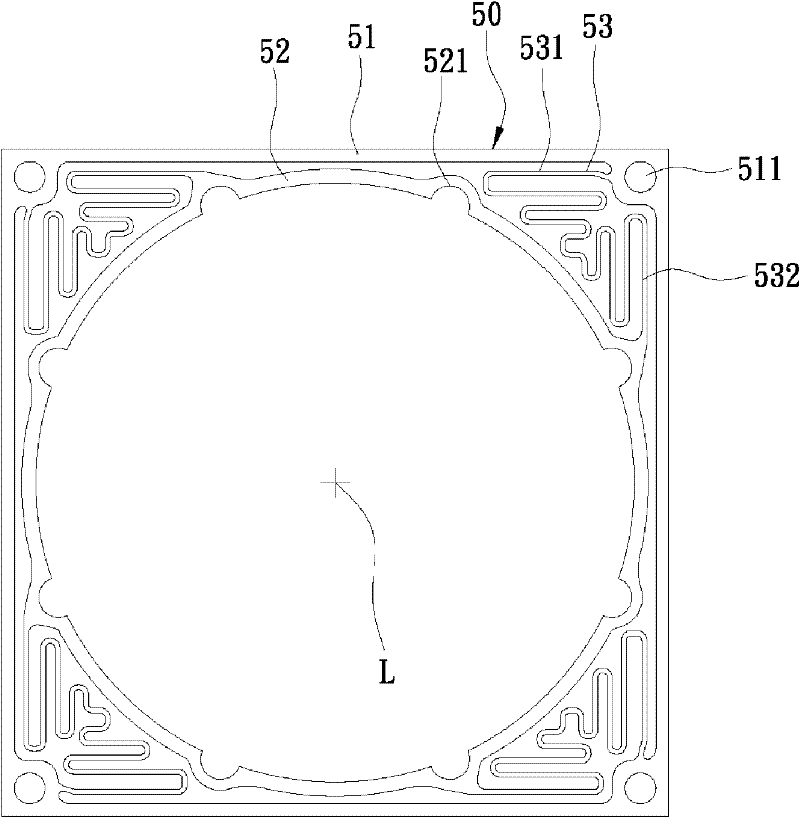
[0017] Such as figure 2 and Figure 4 As shown, a preferred embodiment of the lens module with switchable focus of the present invention includes a fixing unit 10 , a carrier 20 , a lens unit 30 , an electromagnetic driving unit 40 and a flat elastic piece 50 .

[0018] The fixing unit 10 is composed of a base 11 and a frame 12 to form a hollow shell, and has a space 13 around the optical axis L. The flange 112 formed by the lower through hole 111 , the frame 12 also has an upper through hole 121 corresponding to the lower through hole 111 and a plurality of positioning columns 122 surrounding the inner side of the upper through hole 121 .

[0019] The carrier 20 has a hollow bottom plate 21, a cylindrical portion 22 extending from the bottom plate 21 alon...


PUM


Abstract

The invention relates to a lens module capable of switching focuses. The lens module comprises a fixed unit, a carrier stand, a lens unit, an electromagnetic driving unit and a flat elastic sheet. The fixed unit is provided with a space around an optical axis. The carrier stand is arranged in the space. The lens unit is locked in the carried stand in a screwing manner. The electromagnetic driving unit is equipped with a plurality coil sets and a plurality of magnetic assemblied that are arranged in an annular and staggered manner with the coil sets, and can be used for driving the carried stand and the lens unit to be switched between a long-distance shooting state and a near-distance shooting state. The flat elastic sheet is used for providing elastic force to the carrier stand and the lens unit, and the elastic force is balanced with the magnetic force generated by the electromagnetic driving unit. Therefore, the lens module is small in size, and the parts of the lens module are simplified.

Description

technical field [0001] The invention relates to an optical equipment, in particular to a lens module with switchable focus. Background technique [0002] Such as figure 1 As shown, there is an existing lens device, which includes a frame 1, a base 2 fixed on the frame 1, two magnetic guides 3 fixed inside the frame 1 and the base 2, and a load bearing installed inside the frame 1. The base 4 , the lens 5 screwed to the bearing base 4 , a plurality of coil components 6 installed on the frame 1 and a plurality of magnetic components 7 installed on the bearing base 4 corresponding to the coil components 6 . The frame 1 and the base 2 each have guide slopes 101 , 201 that gradually expand and incline from outside to inside. Through the magnetic field caused by these magnetic components 7 and the effect of the current in these coil components 6, the active force generated will push the bearing seat 4, further drive the lens 5 to move, and complete the zooming action. In additio...

Claims


Application Information

Patent Timeline
Patent Type & Authority Applications(China)
IPC IPC(8): G02B7/04
Inventor 陈盈瑞
Owner ASIA OPTICAL CO INC
Learn More