Electronic part and method of detecting faults therein

A technology of electronic components and fault detection, applied in the direction of measuring electricity, measuring devices, measuring electrical variables, etc., can solve problems such as miniaturization of difficult electronic components 501

Inactive Publication Date: 2012-05-16
PANASONIC CORP
View PDF5 Cites 1 Cited by
  • Summary
  • Abstract
  • Description
  • Claims
  • Application Information

AI Technical Summary

Problems solved by technology

However, since the scan test circuit is equipped with a plurality of flip-flops connected in series, it is difficult to miniaturize the electronic component 501 due to wiring for connecting the shift register.

Method used


Image

  • Electronic part and method of detecting faults therein
  • Electronic part and method of detecting faults therein
  • Electronic part and method of detecting faults therein

Examples


Embodiment Construction

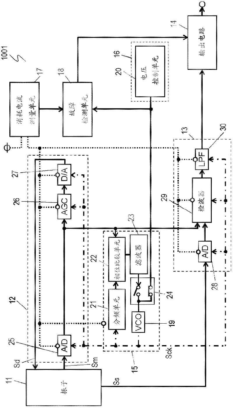
[0026] figure 1 It is a circuit diagram of the electronic component 1001 in Embodiment 1 of this invention. The electronic component 1001 includes: a vibrator 11; a drive circuit 12 that supplies a drive signal Sd to the vibrator 11; a detection signal processing unit 13 that inputs an induction signal Ss from the vibrator 11; an output circuit that outputs an induction signal output from the detection signal processing unit 13 14; the clock frequency generation unit 15 of the output clock signal Sck; the clock frequency control unit 16 of the frequency of the control clock signal Sck; the consumption current measurement unit 17 of the consumption current of the detection drive circuit 12 and the detection signal processing unit 13; and electrically connected to Consumption current measurement unit 17 and failure detection unit 18 of clock frequency control unit 16 . The clock frequency generation unit 15 outputs a clock signal Sck to some of the drive circuit 12 and the det...


PUM


Abstract

An electronic part is equipped with a vibration element, a drive circuit which supplies drive signals to the vibration element, a frequency generation unit, a clock frequency generation unit which outputs clock signals to the drive unit, a clock frequency control unit which controls clock signal frequencies, a consumption current measuring unit which detects the consumption current in the drive unit, and a fault detection unit which is electrically connected to the consumption current measuring unit and to the clock frequency control unit. Changes occur in the consumption current which is detected when the clock frequency control unit changes clock signal frequencies, with the result that the consumption current measuring unit detects the changes in the consumption current detected. The fault detection unit detects faults from changes in clock signal frequencies and from changes in the consumption current. This electronic part has a fault detection function and can be miniaturized.

Description

technical field [0001] The present invention relates to electronic components having a function capable of detecting failures used in automobiles, airplanes, ships, robots, and various other electronic devices, and to a method for detecting failures of the electronic components. Background technique [0002] Figure 8 It is a circuit diagram of a conventional electronic component 501 disclosed in Patent Document 1. FIG. The electronic component 501 includes: a vibrator 1; a drive circuit 2 that supplies a drive signal to the vibrator 1; a detection signal processing circuit unit that inputs a sense signal (sense signal) from the vibrator 1; and a circuit unit that outputs a sense signal output from the detection signal processing unit. output circuit. The driving circuit 2 includes: an analog-to-digital converter 3 that performs analog-to-digital conversion on the monitor signal output from the vibrator 1; an automatic gain amplifier 4 that amplifies the monitor signal outp...

Claims


Application Information

Patent Timeline
Patent Type & Authority Applications(China)
IPC IPC(8): G01R31/00
CPCG01R31/2882G01R31/007G01R31/2829
Inventor 藤井健史黑田启介
Owner PANASONIC CORP
Why Eureka
Try Eureka