
Heat shield element arrangement comprising screw threading means and method for installing a heat shield element

A technology of components and bolts, which is applied in the field of heat shield components to achieve the effect of saving manufacturing costs

Inactive Publication Date: 2015-05-06
SIEMENS AG
View PDF9 Cites 0 Cited by
  • Summary
  • Abstract
  • Description
  • Claims
  • Application Information

AI Technical Summary

Problems solved by technology

[0006] It is especially difficult to guide the fastening bolts into the corresponding threaded holes of the support structure

Method used


Image

  • Heat shield element arrangement comprising screw threading means and method for installing a heat shield element
  • Heat shield element arrangement comprising screw threading means and method for installing a heat shield element
  • Heat shield element arrangement comprising screw threading means and method for installing a heat shield element

Examples


Embodiment Construction

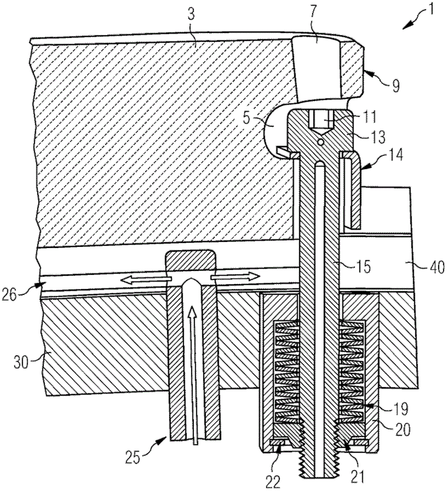
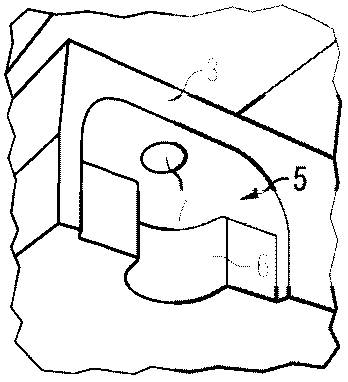
[0028] figure 1 and figure 2 A partial cross-sectional view of a known heat shield element arrangement 1 is shown.

[0029] In the known heat shield element arrangement 1 , the heat shield elements 3 or so-called bricks are fastened to the support structure 30 by means of a total of four screw connections. This relates in particular to vault tiles or samples of heat shield elements.

[0030] Formed in the sides of the heat shield element 3 are recesses or pockets 5 with side recesses 6 into which a screw 15 and a nut 13 can be inserted from the side. Below the screw cap 13 there is a pressure divider or washer 14 which distributes the pressure over a larger area and thus protects the ceramic body of the heat shield element 3 .

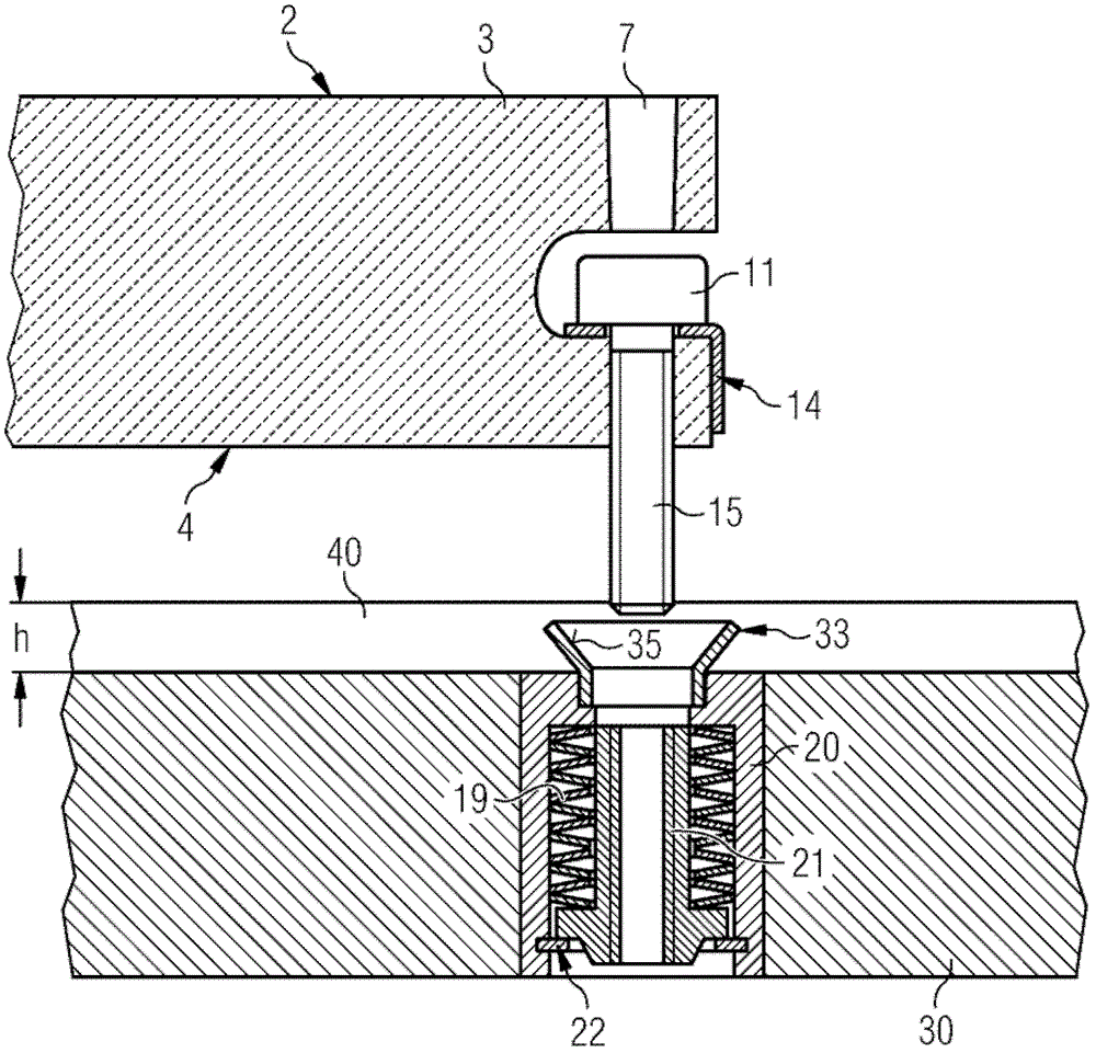
[0031] According to the prior art, the heat shield element 3 with all four installed bolts 15 and the voltage divider 14 must now be installed vertically in the support structure 30, the four screw rods 15 must penetrate into four correspondingly l...


PUM


Abstract

The arrangement has multiple of heat shield elements (3) arranged adjacent to each other at a supporting structure (30). The heat shield elements are fixed at the supporting structure using a screwing shaft (15) in a laminated spring packet (19) that is provided in the supporting structure. The packet provided in the supporting structure is equipped with a funnel shaped screw threading unit (33), into which the fixing screw is guided and inserted. The funnel shaped screw threading unit is fixed at the laminated spring packet in a force fit manner. An independent claim is also included for a method for mounting the heat shield element arrangement.

Description

technical field [0001] The invention relates to a heat shield element arrangement with a heat shield element, a screw lead-through, a method for mounting said heat shield element in a heat shield element arrangement and a method with the features described in the individual independent claims Application of the heat shield element arrangement of the features described in the preamble of . Background technique [0002] To be able to withstand temperatures between 1000°C and 1600°C, effective ceramic heat shields are used in many technical applications. In particular, turbine heat shields such as gas turbines and turbine engines, which are used in power plants and large aircraft, have relatively large surfaces in the interior of their combustion chambers that are protected by the heat shield. Due to the thermal expansion and the large design dimensions, the heat shield has to be composed of a large number of individual heat shield elements made of ceramic, which are spaced fr...

Claims


Application Information

Patent Timeline
Patent Type & Authority Patents(China)
IPC IPC(8): F23R3/00
CPCF23R3/007F23M5/04
Inventor A.贝彻A.克鲁格M.林克W.谢特曼G.西蒙T-D.滕拉姆M.特蒂尔特S.格伦德尔
Owner SIEMENS AG
Learn More