Fibrous material conveying device

A technology for conveying devices and materials, applied in the field of biomass-to-fuel ethanol, can solve problems such as increasing equipment investment costs, and achieve the effects of being beneficial to activation, simple device, and reducing equipment investment costs

Active Publication Date: 2013-11-20
CHINA PETROLEUM & CHEM CORP +1
View PDF2 Cites 0 Cited by
  • Summary
  • Abstract
  • Description
  • Claims
  • Application Information

AI Technical Summary

Problems solved by technology

In the above-mentioned methods, the closed plug is formed by extrusion of a piston or a cone plug, which not only makes the raw material withstand high temperature and pressure to cause hardening or keratinization, but also increases the investment cost of the equipment.

Method used


Image

  • Fibrous material conveying device
  • Fibrous material conveying device

Examples


Embodiment Construction

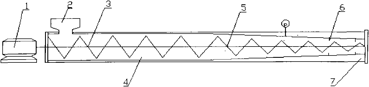
[0019] The structure of the fiber material conveying device of the present invention will be further described below in conjunction with the accompanying drawings.

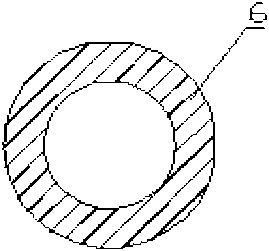
[0020] Such as figure 1 As shown, the fiber material conveying device of the present invention includes: a hopper 2 arranged at the feed end above the screw barrel 4, and the screw barrel 4 is provided with a screw assembly, namely an equal-diameter screw 3 and a conical screw 5, and the equal-diameter screw 3 Connected to motor 1. The pipe wall of the screw barrel 4 is divided into a sandwich structure 7 of an inner wall and an outer wall, and the interlayer is passed into a cooling liquid, and the amount of the cooling liquid reaches the maximum near the discharge end of the conical screw 5, and close to the discharge port of the screw barrel 4. A plurality of annular baffles 6 perpendicular to the cylinder axis are provided.

[0021] The fiber material conveying device provided by the invention adopts a singl...


PUM


Abstract

The invention discloses a fibrous material conveying device. The device which comprises a hopper, a screw cylinder and a screw assembly is characterized in that: the hopper which is positioned above the screw cylinder is on the feeding end of the screw cylinder; screws are arranged in the screw cylinder; the tube wall of the screw cylinder is of an interlayer structure comprising an inter wall and an outer wall; a liquid coolant is accessed to the interlayer; and at least one annular baffle plate perpendicular to the axis of the screw cylinder is arranged on the screw cylinder within a range from the discharging end to 3-50% of the length of the screw cylinder. The device of the invention has the advantages of guarantee of the continuous and stable convey of the material to a high temperature high pressure reactor, high temperature steam back-spray prevention, fibrous material keratinization reduction, simplicity, and simple operation.

Description

technical field [0001] The invention relates to the field of fuel ethanol produced from biomass, in particular to a raw material conveying device for a lignocellulose pretreatment device. Background technique [0002] The production of fuel ethanol from crop stalks and other plants has become a new resource and energy industry chain. Due to the complex composition of crop straw and forestry residues, the water content, hardness, and crush resistance of different crops are very different, which brings great difficulties to the fiber pretreatment process. In the pretreatment process, it is often necessary to transport solid materials from a normal temperature and pressure environment to a high temperature and high pressure device for processing. The traditional method is to set up a chamber with a pressurization and pressure relief device for intermittent treatment, but this method is inefficient, consumes a lot of energy, and cannot meet the continuous operation of industria...

Claims


Application Information

Patent Timeline
Patent Type & Authority Patents(China)
IPC IPC(8): B01J3/02
Inventor 王鑫黎元生乔凯张全
Owner CHINA PETROLEUM & CHEM CORP
Why Eureka
Try Eureka