Suspension board with circuit and manufacturing method thereof
A technique for suspending substrates and substrates, which is applied to the formation of electrical connections of printing components, configuration/installation of recording heads, and instruments, and can solve problems such as the difficulty of compacting suspension substrates
- Summary
- Abstract
- Description
- Claims
- Application Information
AI Technical Summary
Problems solved by technology
Method used
Image

Examples
no. 1 Embodiment approach
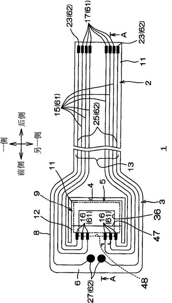
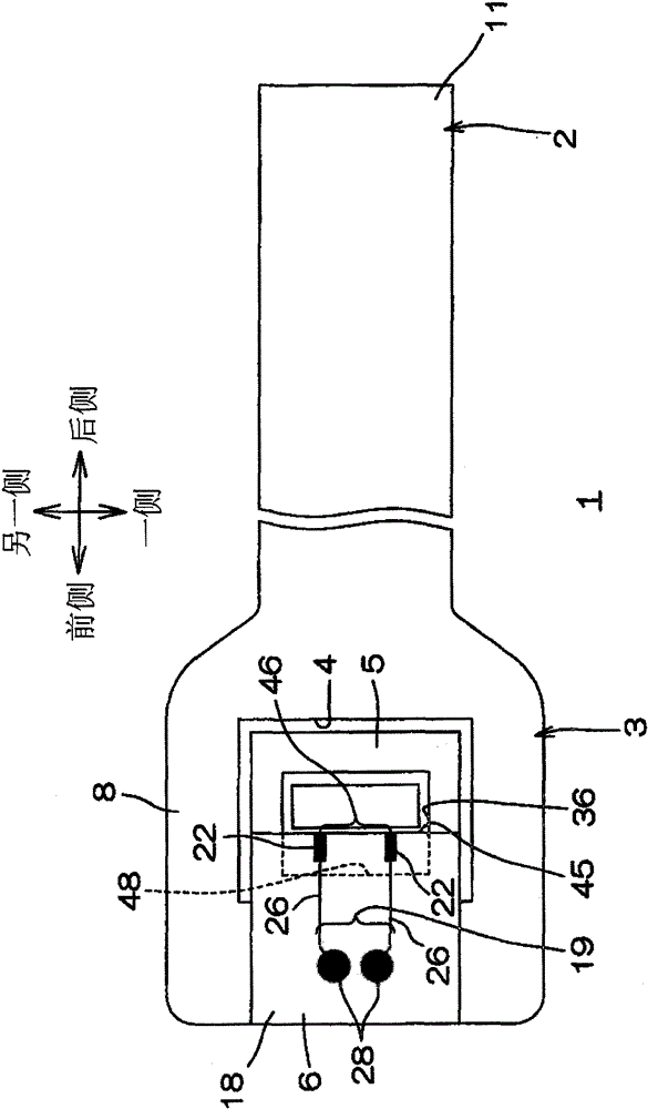
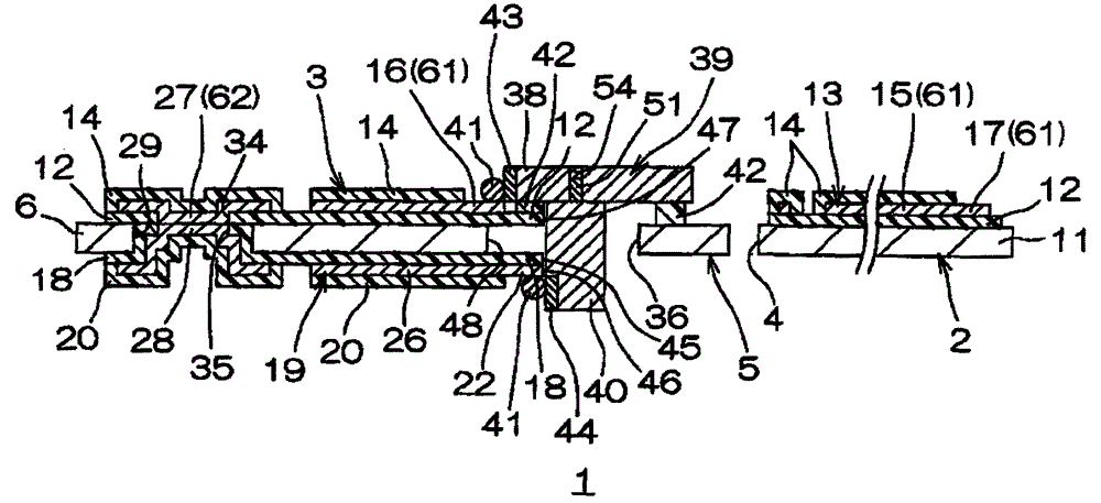
[0044] figure 1 It is a plan view showing the first embodiment of the suspension board with circuit of the present invention, figure 2 express figure 1 Bottom view of the suspension board with circuitry shown, image 3 yes means figure 1 A-A sectional view of the suspension board with circuit shown.
[0045] In addition, in figure 1 In the figure, the first insulating cover layer 14 (described later) is omitted in order to clearly show the relative arrangement of the first conductive pattern 13 (described later). In addition, in figure 2 In the figure, the second insulating cover layer 20 (described later) is omitted in order to clearly show the relative arrangement of the second conductive pattern 19 (described later).
[0046] Such as figure 1 As shown, the suspension board with circuit 1 is formed in the shape of a flat belt extending in the longitudinal direction, and integrally has a wiring portion 2 disposed on the other side (hereinafter referred to as the r...
no. 2 Embodiment approach
[0145] Figure 6 Showing a second embodiment of the suspension board with circuit of the present invention, it is a cross-sectional view of a slider mounting region.
[0146] In the first embodiment described above, the rear end portion of the second insulating base layer 18 is arranged so as to overlap the rear end portion of the first insulating base layer 12 when projected in the thickness direction, and the element-side terminal 22 is provided on the second base layer. the back side of the insulating layer 18, but in the second embodiment, such as Figure 6 As shown, the rear end portion of the second insulating base layer 18 is arranged to cover the through opening 36 of the metal supporting substrate 11 when projected in the thickness direction, and the element-side terminal 22 is arranged to penetrate the second insulating base layer 18 in the thickness direction. The mode is formed as a so-called flying lead.
[0147] In the second embodiment, when viewed from the fr...
no. 3 Embodiment approach
[0154] Figure 7 Showing a third embodiment of the suspension board with circuit of the present invention, it is a cross-sectional view of a slider mounting region.
[0155] In the above-mentioned first embodiment, the element-side terminal 22 is provided on the back surface of the second insulating base layer 18 so that the edge 46 thereof is substantially flush with the edge 45 of the second insulating base layer 18 . 3 In the embodiment, such as Figure 7 As shown, the element-side terminal 22 is formed as a so-called flying lead so as to protrude rearward from the rear end portion of the second insulating base layer 18 .
[0156] In the third embodiment, the element-side terminal 22 protrudes to the middle of the penetration opening 36 of the metal supporting board 11 when projected in the thickness direction.
[0157] In addition, when projected in the thickness direction, the through opening 36 exposed from the second insulating base layer 18 and the element-side termi...
PUM
| Property | Measurement | Unit |
|---|---|---|
| thickness | aaaaa | aaaaa |
| thickness | aaaaa | aaaaa |
| thickness | aaaaa | aaaaa |
Abstract
Description
Claims
Application Information
 - R&D
- Intellectual Property
- Life Sciences
- Materials
- Tech Scout
- Unparalleled Data Quality
- Higher Quality Content
- 60% Fewer Hallucinations
Browse by: Latest US Patents, China's latest patents, Technical Efficacy Thesaurus, Application Domain, Technology Topic, Popular Technical Reports.
© 2025 PatSnap. All rights reserved.Legal|Privacy policy|Modern Slavery Act Transparency Statement|Sitemap|About US| Contact US: help@patsnap.com