
Mining hydraulic re-railing machine

A hydraulic and mine-used technology, which is applied in the field of rerailing devices, can solve problems such as difficulties in rerailing mine vehicles, and achieve the effects of light weight, easy operation and small size

Inactive Publication Date: 2012-05-09
SHANXI COKING COAL GROUP
View PDF7 Cites 5 Cited by
  • Summary
  • Abstract
  • Description
  • Claims
  • Application Information

AI Technical Summary

Problems solved by technology

[0003] The purpose of the present invention is to solve the problem of difficult rerailing of existing mining vehicles, and to provide a mine hydraulic rerailing machine

Method used


Image

  • Mining hydraulic re-railing machine
  • Mining hydraulic re-railing machine
  • Mining hydraulic re-railing machine

Examples


Embodiment Construction

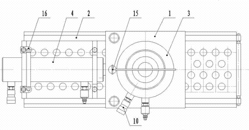
[0011] Below in conjunction with accompanying drawing, mine hydraulic rerailing machine described in the present invention will be clearly and completely described.

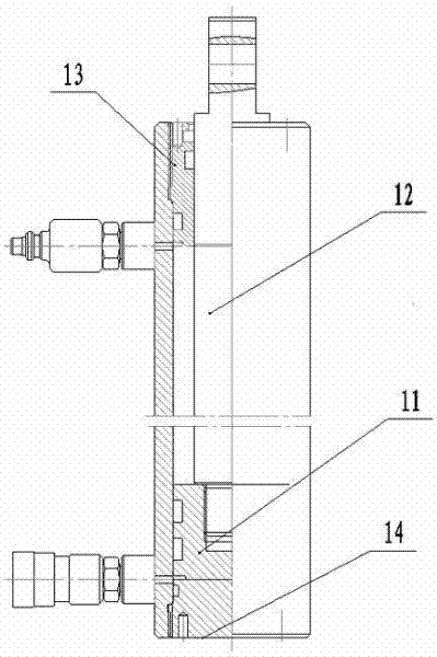
[0012] A mining hydraulic rerailing machine according to the present invention includes a moving rail 1, a static rail 2, a lifting cylinder 3 and a translation cylinder 4, the moving rail 1 and the static rail 2 are slidably connected, and the lifting cylinder 3 is fixed on the moving rail On the upper surface of 1, one end of the translation cylinder 4 is fixed to the static rail 2, and the other end is hinged to the side of the moving rail 1.

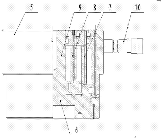
[0013] The lifting cylinder can adopt a three-stage oil cylinder, and its structure includes a cylinder body 5, a cylinder head 6, and a first-stage cylinder 7, a second-stage cylinder 8 and a third-stage cylinder 9 located inside the cylinder body 5. The cylinder body 5 is provided with a fast Connector 10. The lifting cylinder is the main lifting cylinder. If the dis...


PUM


Abstract

The invention aims to resolve the problem of difficulty in re-railing of existing mining vehicles, and provides a mining hydraulic re-railing machine, which comprises a moving rail, a fixed rail, a lifting cylinder and a translational cylinder. The moving rail and the fixed rail are in slidable connection, the lifting cylinder is fixed onto the upper surface of the moving rail, one end of the translational cylinder is fixed with the fixed rail, and the other end of the translational cylinder is hinged with the lateral side of the moving rail. When the mining hydraulic re-railing machine is used, the fixed rail is placed below a vehicle, and the lifting cylinder is controlled to ascend to jack up derailed vehicle. When the vehicle is lifted to a certain height, the translational cylinder is controlled to extend out to push the vehicle to a proper position, and then the lifting cylinder is withdrawn to stably place the vehicle on the track, so that re-railing of the vehicle is completed. By means of the new combined re-railing technology of vertical lifting and transverse translation, lifting and resetting are completed synchronously, and dangers of tilting and rolling over the vehicle in re-railing are eliminated.

Description

technical field [0001] The invention relates to an auxiliary transportation machine, in particular to a rerailing device. Background technique [0002] During the transportation operation of coal mine vehicles, due to collisions, line quality and other reasons, the vehicles derailed and fell off the track. The traditional way for vehicles to go on the track is to use the top slide (the coal mine safety regulations stipulate that it is prohibited to use when rerailing), chain hoists, etc. The tools are put on the road manually, which is cumbersome, labor-intensive, low safety factor, time-consuming and labor-intensive. Contents of the invention [0003] The purpose of the present invention is to solve the problem of difficult rerailing of existing mining vehicles and provide a mining hydraulic rerailing machine. [0004] In order to solve the above problems, the mining hydraulic rerailing machine of the present invention includes: a moving rail, a static rail, a lifting cy...

Claims


Application Information

Patent Timeline
IPC IPC(8): B61K5/06
Inventor 韩敬魏生强郭兵
Owner SHANXI COKING COAL GROUP
Learn More