
Switch power supply and divider therefor

A technology of switching power supply and instrument, applied in the direction of instruments, electrical components, adjusting electrical variables, etc., can solve the problems of high cost, complex circuit structure, unstable compensation function, etc.

Active Publication Date: 2012-05-02
BCD (SHANGHAI) MICRO ELECTRONICS LTD
View PDF4 Cites 5 Cited by
  • Summary
  • Abstract
  • Description
  • Claims
  • Application Information

AI Technical Summary

Problems solved by technology

[0003] The traditional switching power supply needs to add an additional line voltage compensation circuit, the circuit structure is complex, the cost is high, and the compensation function is unstable

Method used


Image

  • Switch power supply and divider therefor
  • Switch power supply and divider therefor
  • Switch power supply and divider therefor

Examples


Embodiment Construction

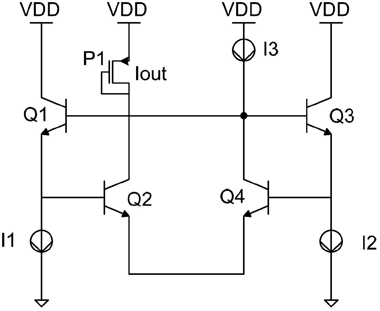
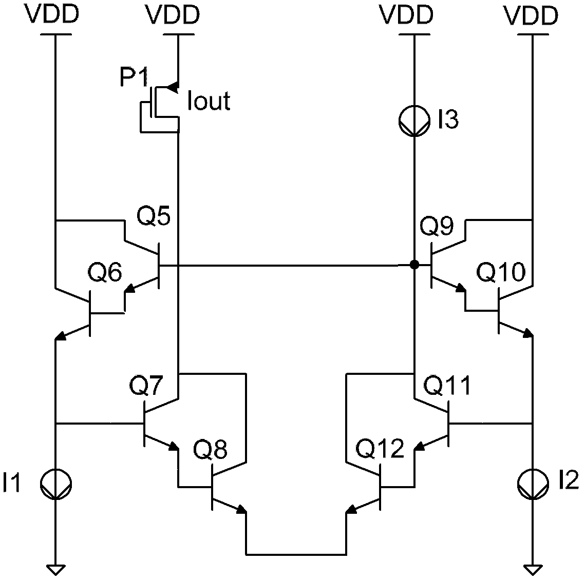
[0033] An embodiment of the present application provides a divider for a switching power supply, the divider includes: a first set of bipolar transistors, a second set of bipolar transistors, a third set of bipolar transistors, and a fourth set of bipolar transistors, Wherein, the control terminal of the first bipolar transistor set is connected to the control terminal of the third bipolar transistor set, and the control terminal of the first bipolar transistor set is connected to the fourth bipolar transistor set The first end of the set is connected, the first end of the first bipolar transistor set is connected to a DC power supply, and the current flowing through the second end is the first input current I 1 ; the control end of the second bipolar transistor set is connected to the second end of the first bipolar transistor set, the first end of the second bipolar transistor set is connected to the DC power supply, and the The second end of the second bipolar transistor se...


PUM


Abstract

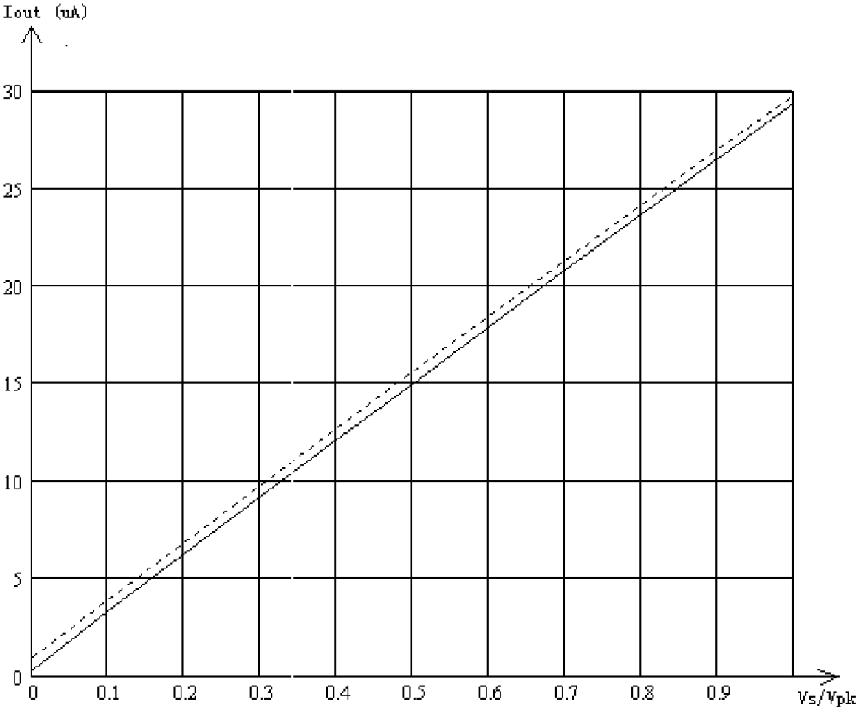
The invention discloses a divider for a switch power supply, which comprises four groups of bipolar transistor sets, wherein an output current and an input current of the divider have the following relationship, wherein if I1 is a current signal corresponding a sampling signal of a linear voltage peak value signal, a formula of Iout_min=(n*I3 / beta)m is obtained according to the relationship among a base current, a collector current and an emitter current of the bipolar transistor, wherein beta is an amplification factor of the bipolar transistor sets, and m is the cascade quantity of bipolar transistors in the bipolar transistor sets. Known from the expression of Iout_min and Iout_max, the higher the linear voltage is, the lower the n is, and the smaller the Iout_min and the Iout_max are, thus the divider for the switch power supply has a function of online compensation. Therefore, a linear voltage compensation circuit does not need to be additionally arranged in the switch power supply, circuit structure is simplified and cost is reduced.

Description

technical field [0001] The present application relates to the technical field of switching power supplies, in particular to a divider for a switching power supply, that is, a switching power supply. Background technique [0002] In the switching power supply, due to the existence of the power switching tube, the power switching tube has a turn-off delay, and the output voltage of the switching power supply has an error, and the error is proportional to the input line voltage, usually in the control of the switching power supply. A line voltage compensation circuit is added to the periphery of the circuit, so that when the switching power supply inputs different line voltages, the output current is consistent. [0003] The traditional switching power supply needs to add an additional line voltage compensation circuit, the circuit structure is complicated, the cost is high, and the compensation function is unstable. Contents of the invention [0004] In order to solve the a...

Claims


Application Information

Patent Timeline
IPC IPC(8): H02M3/157H02M3/335
Inventor 陈泽强刘娜任雪刚段建华徐思远
Owner BCD (SHANGHAI) MICRO ELECTRONICS LTD
Learn More