Eureka AIR delivers breakthrough ideas for toughest innovation challenges, trusted by R&D personnel around the world.

Storage battery reduction charge-discharge converter circuit

A technology for charging and discharging batteries, applied in the field of battery formation, can solve the problems of uncontrollable, difficult to detect, and high cost, and achieve the effects of reducing volume and weight, improving conversion efficiency, and reducing working pressure

Inactive Publication Date: 2012-05-02
NORTH CHINA ELECTRIC POWER UNIV (BAODING)
View PDF3 Cites 63 Cited by
  • Summary
  • Abstract
  • Description
  • Claims
  • Application Information

AI Technical Summary

Problems solved by technology

The traditional silicon controlled rectifier full bridge and the formation power supply device composed of polarity switching circuit can meet the above working mode and realize the charge and discharge formation function, but the disadvantage is that the power conversion adopts the power frequency phase control method, which leads to the distortion of the AC current waveform Serious, the harmonic component is large; the power factor is low and uncontrollable; the power frequency transformer is used to transform the voltage and electrical isolation, and the loss is large, resulting in low energy conversion efficiency of the whole machine, and a large amount of non-ferrous metals are consumed, and the cost is high
During formation, each bidirectional DC / DC converter is connected to a group of battery packs composed of multiple batteries connected in series. However, the entire DC system, the secondary DC / DC bidirectional conversion main circuit and all connected batteries are in the same voltage The coupling system covers a wide range of electrical connection points and is distributed throughout the chemical plant. When the system is grounded at one point, it is difficult to detect and detect the specific grounding point, which is likely to cause accident hazards; cause system short circuit failure
Therefore, the use of non-isolated secondary DC / DC bidirectional conversion main circuit will significantly reduce the safety, reliability and economy of the system

Method used


Image

  • Storage battery reduction charge-discharge converter circuit
  • Storage battery reduction charge-discharge converter circuit
  • Storage battery reduction charge-discharge converter circuit

Examples


Embodiment Construction

[0035] The present invention will be described in further detail below in conjunction with the accompanying drawings.

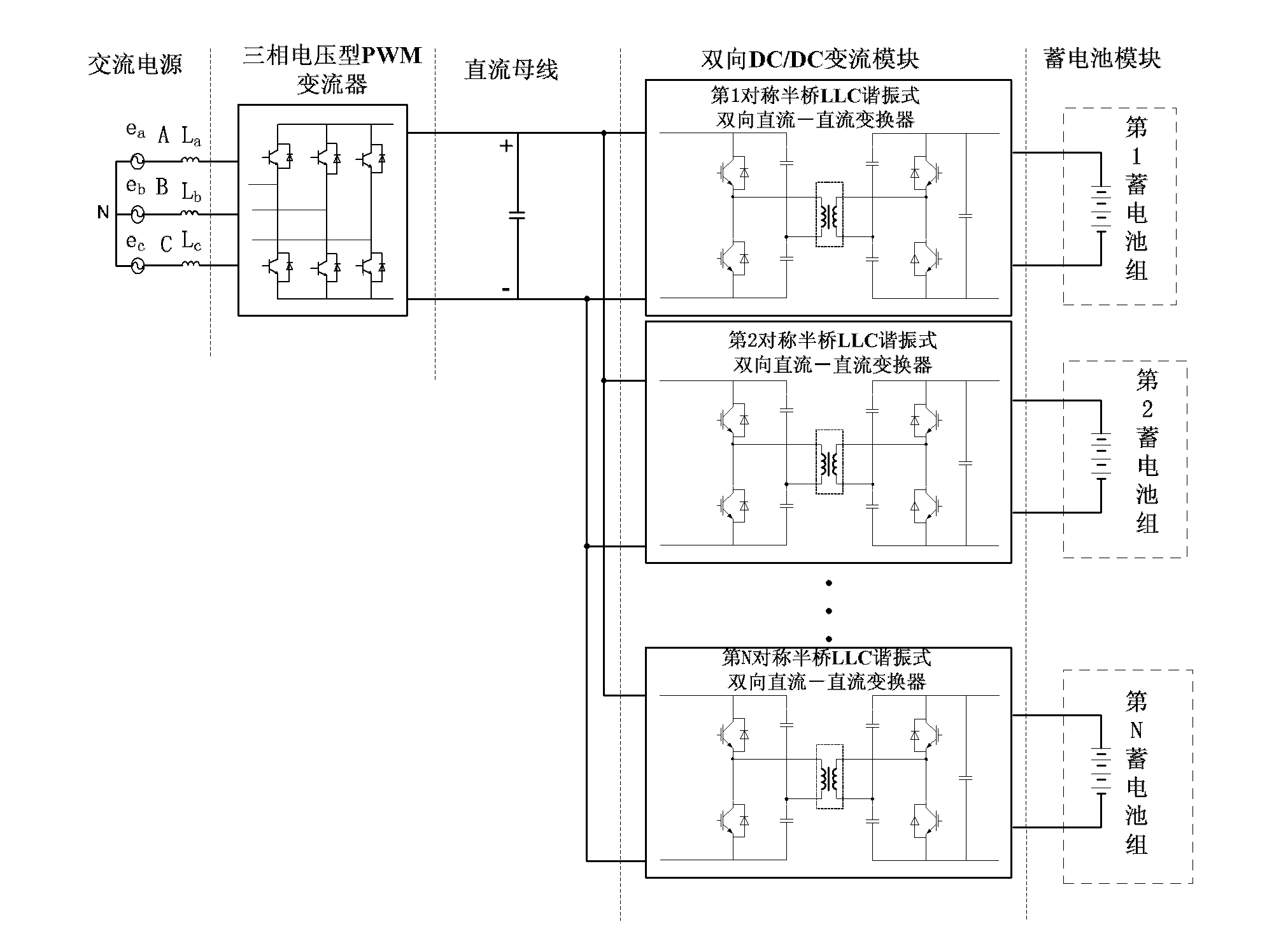
[0036] Such as figure 1 As shown, the present invention discloses a charge-discharge conversion circuit for accumulators, using a three-phase voltage-type PWM converter as the first-stage power conversion circuit to realize energy conversion between the AC power grid and the public DC bus, referred to as "AC / DC primary conversion"; a symmetrical half-bridge LLC resonant bidirectional DC-DC converter is used as the second-stage power conversion circuit to realize energy conversion between the public DC bus and the battery pack, referred to as "DC / DC secondary conversion" ;

[0037] The structure of the battery charging and discharging converter circuit is as follows: AC power supply, three-phase voltage type PWM converter, DC bus, bidirectional DC / DC converter module and battery module are connected in series;

[0038] The bidirectional DC / DC converter modu...


PUM


Abstract

The invention discloses a storage battery reduction charge-discharge converter circuit, belonging to the technical field of storage battery reduction. The structure is characterized in that an alternating-current power supply, a three-phase-voltage-type PWM (pulse width modulation) converter, a direct-current bus, a dual-direction DC / DC (direct-current / direct-current) converter module and a storage battery module are connected in series. The storage battery reduction charge-discharge converter circuit provided by the invention has the beneficial effects that the three-phase-voltage-type PWM converter has high power coefficient and low harmonic pollution, dual-direction DC / DC converter module improves the conversion efficiency, dynamic property and power density of a storage battery reduction charge-discharge device, and the volume and weight of a reduction charge-discharge device are reduced; and at the same time, the utilization efficiency of energy is improved, thus the safety, reliability and economy of the system are improved effectively.

Description

technical field [0001] The invention belongs to the technical field of accumulator formation, and in particular relates to an accumulator formation charging and discharging converter circuit. Background technique [0002] Battery formation is an important link in the battery production process. The positive and negative electrodes of a chemical power supply are composed of active materials and "collectors" for support and conduction. They are generally sheet-like porous bodies, called plates; active materials are often not directly added to the current collector when making plates. Instead, the raw materials are made into glue paste and coated on the grid, or the raw materials are poured into glass fiber tubes, and the plates at this time are generally called "green plates". The so-called formation refers to the electrochemical reaction process in which the raw plate of the battery is transformed into a charged state through charging in the electrolyte, impurities are remov...

Claims


Application Information

Patent Timeline
IPC IPC(8): H02J7/10H02M3/335
CPCY02B70/1433Y02B70/10
Inventor 颜湘武董清张波
Owner NORTH CHINA ELECTRIC POWER UNIV (BAODING)
Why Eureka
Eureka Blog
Learn More