Two-shaft automatic turntable structure with built-in air ducts

An automatic turntable and air duct technology, applied in the field of measurement, can solve the problems of limiting the angular movement range, damaging the DUT and the turntable, failing to meet the test requirements, etc., and achieving the effect of solving winding damage

Inactive Publication Date: 2014-04-09
FLIGHT AUTOMATIC CONTROL RES INST
View PDF4 Cites 0 Cited by
  • Summary
  • Abstract
  • Description
  • Claims
  • Application Information

AI Technical Summary

Problems solved by technology

When the angular motion test is performed on the two-axis automatic turntable for the tested part that needs ventilation and heat dissipation, the air duct for the air supply to the tested part is placed outside the turntable and directly connected to the tested part. When used on the automatic turntable , when the azimuth axis and the tilt axis rotate at a large angle, the air duct is easily wound on the turntable, causing the turntable to stop and damage the air duct beyond the torque range. In severe cases, it will also damage the tested part and the turntable
At the same time, the external air duct also limits the range of motion of the angle, failing to meet the test requirements of continuous rotation and angular rate

Method used


Image

  • Two-shaft automatic turntable structure with built-in air ducts
  • Two-shaft automatic turntable structure with built-in air ducts
  • Two-shaft automatic turntable structure with built-in air ducts

Examples


Embodiment Construction

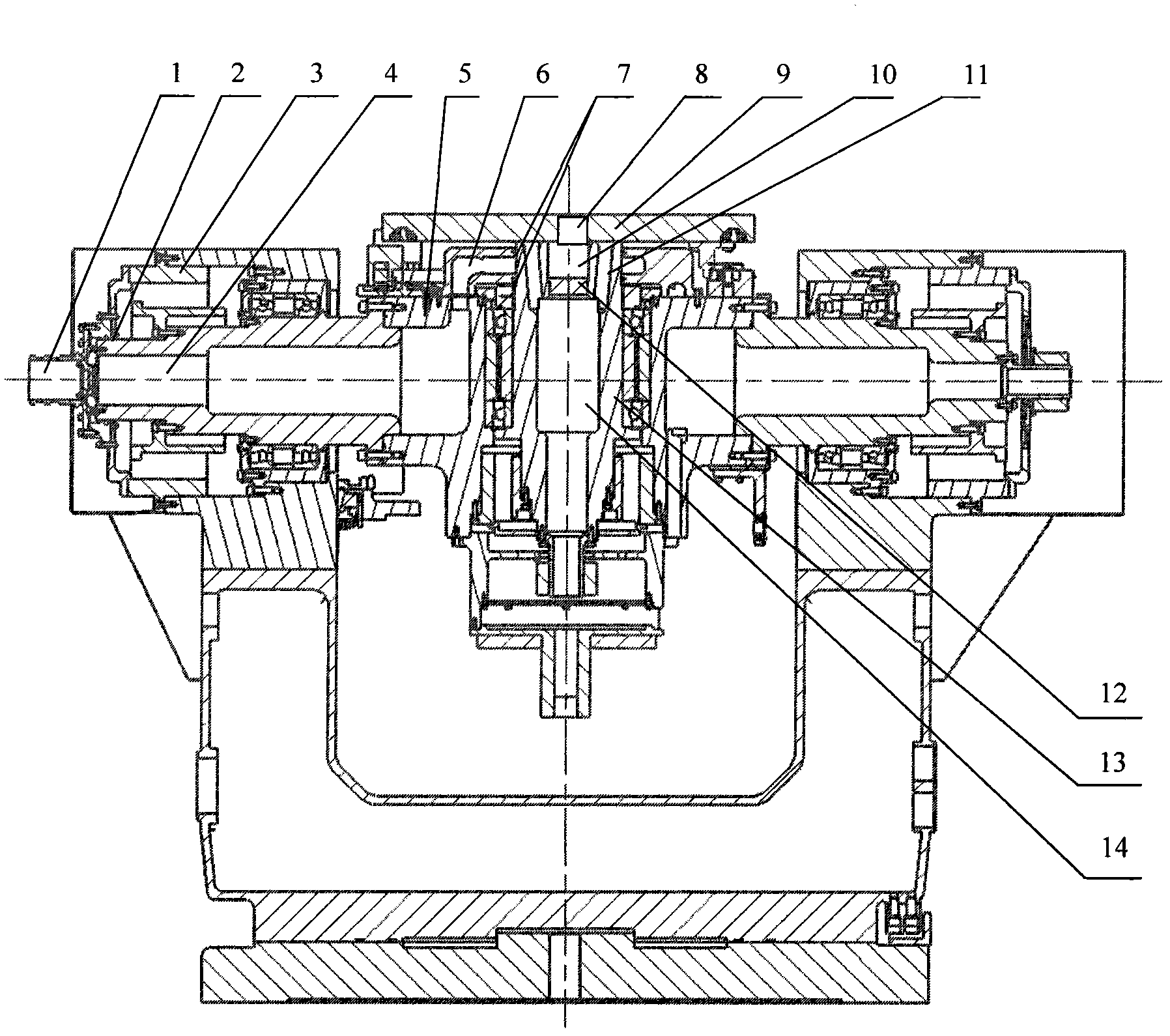
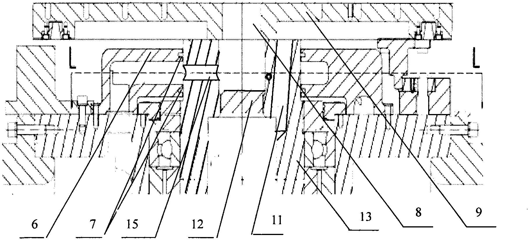
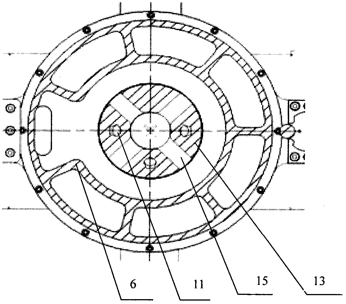
[0012] The present invention will be described in detail below in conjunction with the accompanying drawings.

[0013] The external air supply pipe is connected with the air inlet 1 of the turntable, and the air volume is introduced into the built-in air duct of the turntable. The air inlet 1 is fixed on the shaft end housing 3 of the inclined shaft 4 of the turntable, and a rotating sealing ring 2 is added between the air inlet 1 and the inclined shaft 4, forming a dynamic and static connection between the air inlet 1 and the inclined shaft 4, achieving The function that the inclined shaft 4 rotates continuously while continuously supplying air. The inclined shaft 4 is a hollow structure to form an air duct. The inclined shaft 4 is connected to the housing 5 of the azimuth shaft system. The azimuth housing 5 is equipped with an annular air box 6. One end of the annular air box 6 is connected to the hollow air duct of the inclined shaft 4. In communication, the other end of t...


PUM


Abstract

The invention belongs to the technical field of measurement, and relates to a two-shaft automatic turntable structure with built-in air ducts. The structure is used for ventilating measured parts and dissipating the heat of the measured parts. By building the air ducts in a turntable shaft and realizing that the air ducts pass through the inner and outer shafts by utilizing two-stage rotary joints of the air ducts, the structure adapts to the ventilation under the condition of continuous rotation of the two shafts; one ventilating rotary joint is installed at one side of a tilting shaft system, and the other side is used for a conducting ring and other electrical channels; the other rotary joint is installed in the middle of an azimuth shaft by adopting a unique air box structure; the shaft end part of the azimuth shaft is reserved for the conducting ring and other electrical channels; and the rotary joints enable the air ducts to complete dynamic and static transformation. The problem of collision between the air ducts of the azimuth shaft system and the electrical channels (the conducting ring and cables) is solved by adopting the divided chamber structure; and the two shafts can provide positioning at any angle, thus ensuring air supply while realizing infinite rotation, and meeting the test requirements for continuous rotation and the angular rate.

Description

technical field [0001] The invention belongs to the technical field of measurement, and relates to a two-axis automatic turntable structure used for a built-in air duct for a measured piece requiring ventilation and heat dissipation. Background technique [0002] At present, due to the small size and high power density of many tested products, ventilation and heat dissipation are required during use, and the test under angular motion conditions must rely on a turntable. When the angular motion test is performed on the two-axis automatic turntable for the tested part that needs ventilation and heat dissipation, the air duct for the air supply to the tested part is placed outside the turntable and directly connected to the tested part. When used on the automatic turntable , when the azimuth axis and the tilt axis rotate at a large angle, the air duct is easily wound on the turntable, causing the turntable to stop beyond the torque range and damage the air duct. In severe cases...

Claims


Application Information

Patent Timeline
Patent Type & Authority Patents(China)
IPC IPC(8): G01D11/00G01D11/30
Inventor 毛荣辉焦振丽
Owner FLIGHT AUTOMATIC CONTROL RES INST
Why Eureka
Try Eureka