
System and method for locating ultra-deepwater underwater stand pipe supporting pontoon

A technology for positioning systems and buoys, which is applied to underwater structures, underwater operating equipment, barges/flat-bottomed boats, etc. It can solve the problems of high risk factor, unsuitability in deep sea, and poor controllability of the position of support buoys in water. To achieve the effect of staying steadily and reducing the range of motion

Inactive Publication Date: 2012-05-02
DALIAN UNIV OF TECH
View PDF5 Cites 10 Cited by
  • Summary
  • Abstract
  • Description
  • Claims
  • Application Information

AI Technical Summary

Problems solved by technology

[0004] At present, a common method is to directly sink the standpipe support buoy into the preset position underwater. The advantage of this engineering method is that it is simple and easy to implement, but the controllability of the position of the riser support buoy in the water is too poor. Unable to freely adjust the position of the riser supporting the buoy in the water, the risk factor is high
In addition, there are pilings on the seabed to support the buoys, but this method is only suitable for shallow seas, and it is not suitable for deep seas
[0005] Due to the existence of the above problems, in the ultra-deep sea environment, the traditional positioning method for the support buoy of the riser in the water has been unable to meet the design requirements

Method used


Image

  • System and method for locating ultra-deepwater underwater stand pipe supporting pontoon
  • System and method for locating ultra-deepwater underwater stand pipe supporting pontoon
  • System and method for locating ultra-deepwater underwater stand pipe supporting pontoon

Examples


Embodiment Construction

[0028] The present invention will be further described below with reference to the accompanying drawings.

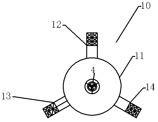
[0029] like figure 1 As shown, the riser support buoy 10 is composed of a central column structure buoy 11 and three cantilever buoys with a rectangular cross-section. The three cantilever buoys are located at the edge of the central column structure buoy 11, and the included angle on the plane is 120°, forming a radial shape. The three cantilever buoys are cantilever buoys A12, cantilever buoys B13 and cantilever buoys C14, and the ends of the three cantilever buoys adopt a truss structure with neutral buoyancy, so that the riser support buoy 10 in the water meets the pre-designed buoyancy, lowering the vertical buoyancy. The tubes support the weight of the pontoon 10, thereby reducing production costs.

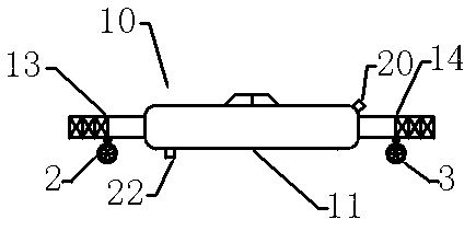
[0030] like figure 2 As shown, the riser support buoy 10 has a umbilical interface 20 on the upper part and an exhaust valve 22 on the lower part.

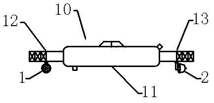
[0031] like ...


PUM


Abstract

The invention discloses a system and method for locating an ultra-deepwater underwater stand pipe supporting pontoon. The system comprises an underwater power locating device and a pontoon tension mooring locating device; and the underwater power locating device comprises a control cable and four thrusters, and the pontoon tension mooring locating device is characterized in that a stand pipe supporting pontoon is vertically moored on a seabed by a tension mooring rope. The four thrusters are respectively arranged at four appointed positions of the stand pipe supporting pontoon to respectively take charge of lifting up and down, moving forwards and backwards and rotating the stand pipe supporting pontoon, and can freely and exactly move the stand pipe supporting pontoon to an underwater appointed position. According to the system for locating the ultra-deepwater underwater stand pipe supporting pontoon, disclosed by the invention, the stand pipe supporting pontoon is located at the underwater appointed position by power and then is fixed on the seabed by the pontoon tension mooring locating device so that the movement amplitude of the stand supporting pontoon can be reduced, and the stand pipe supporting pontoon can very smoothly stop at the underwater appointed position.

Description

technical field [0001] The invention relates to an offshore oil and gas field development technology, in particular to a positioning system and a method for an underwater riser supporting buoy used for the development of an ultra-deep sea oil and gas field. Background technique [0002] In the development of oil and gas fields in the ultra-deep sea (above 1500m in water depth), the marine riser, as the only structure connecting the surface part and the underwater production system, is an important part of the development of offshore oil and gas fields. [0003] In view of the huge challenges of ultra-deep water depth and high pressure, and the serious challenges brought about by the applicability of traditional risers, the current innovative marine riser application concept is to use the underwater riser to support the buoy to support the lower rigid riser, and the lower rigid riser. The bottom end of the pipe is connected with the subsea wellhead, and the top end is connect...

Claims


Application Information

Patent Timeline
IPC IPC(8): E21B43/017B63B35/28B63C11/52
Inventor 黄一甄兴伟张崎刘刚李红霞
Owner DALIAN UNIV OF TECH
Learn More