Construction method of piercing connection joint between steel beam/steel pipe concrete column and reinforced concrete beam

A technology for connecting joints and steel pipe concrete columns, which is applied in the direction of building construction, construction, and building material processing, etc., can solve the problems of complex force and structure, small welding volume space, and many through-hole components, and achieve welding volume space Small size, reduced steel consumption, and good seismic performance

Active Publication Date: 2013-11-27
WUHAN CONSTR ENG
View PDF7 Cites 0 Cited by
  • Summary
  • Abstract
  • Description
  • Claims
  • Application Information

AI Technical Summary

Problems solved by technology

However, as an important beam-column joint in CFST columns, it has evolved from the relatively simple connection between steel beams and CFST columns or the connection between reinforced concrete beams and CFST columns in the past to a CFST column joint that consists of reinforced concrete beams and ring beams. At the same time, there are steel beams connected through the center, and its force and structure are complicated
How to solve the construction difficulties of this node, such as complex structure, many through-hole components, small space for welding, complicated installation, and various processes completed in the same narrow space, so there is an urgent need for a method that combines complex processes and procedures from time to time. Spatially differentiated construction methods reduce construction difficulty, improve efficiency, and reasonably, safely and economically solve the construction problems of the complex structure of steel beam-concrete-filled steel pipe columns and reinforced concrete beams through the center connection joints

Method used


Image

  • Construction method of piercing connection joint between steel beam/steel pipe concrete column and reinforced concrete beam
  • Construction method of piercing connection joint between steel beam/steel pipe concrete column and reinforced concrete beam
  • Construction method of piercing connection joint between steel beam/steel pipe concrete column and reinforced concrete beam

Examples


specific Embodiment approach

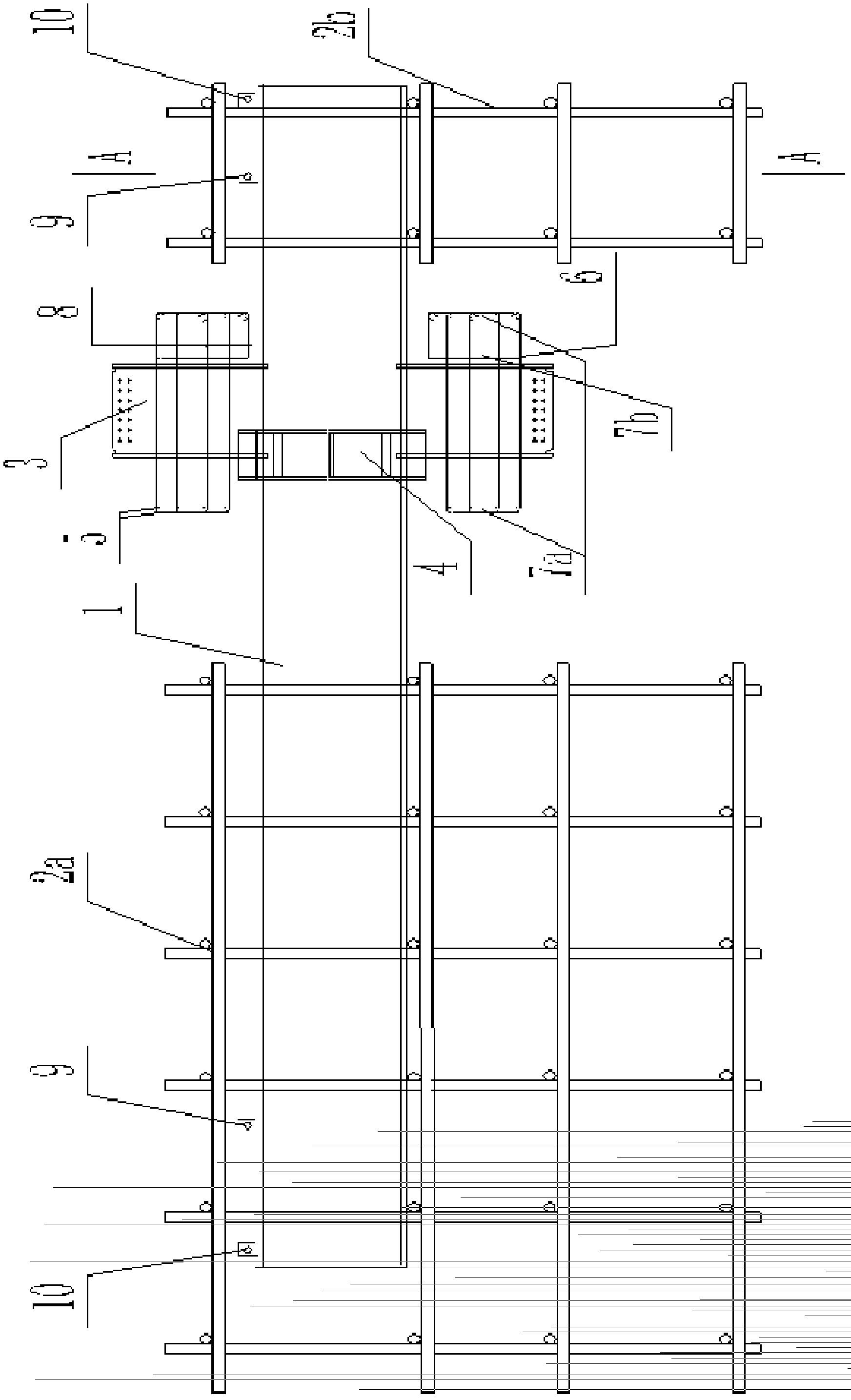
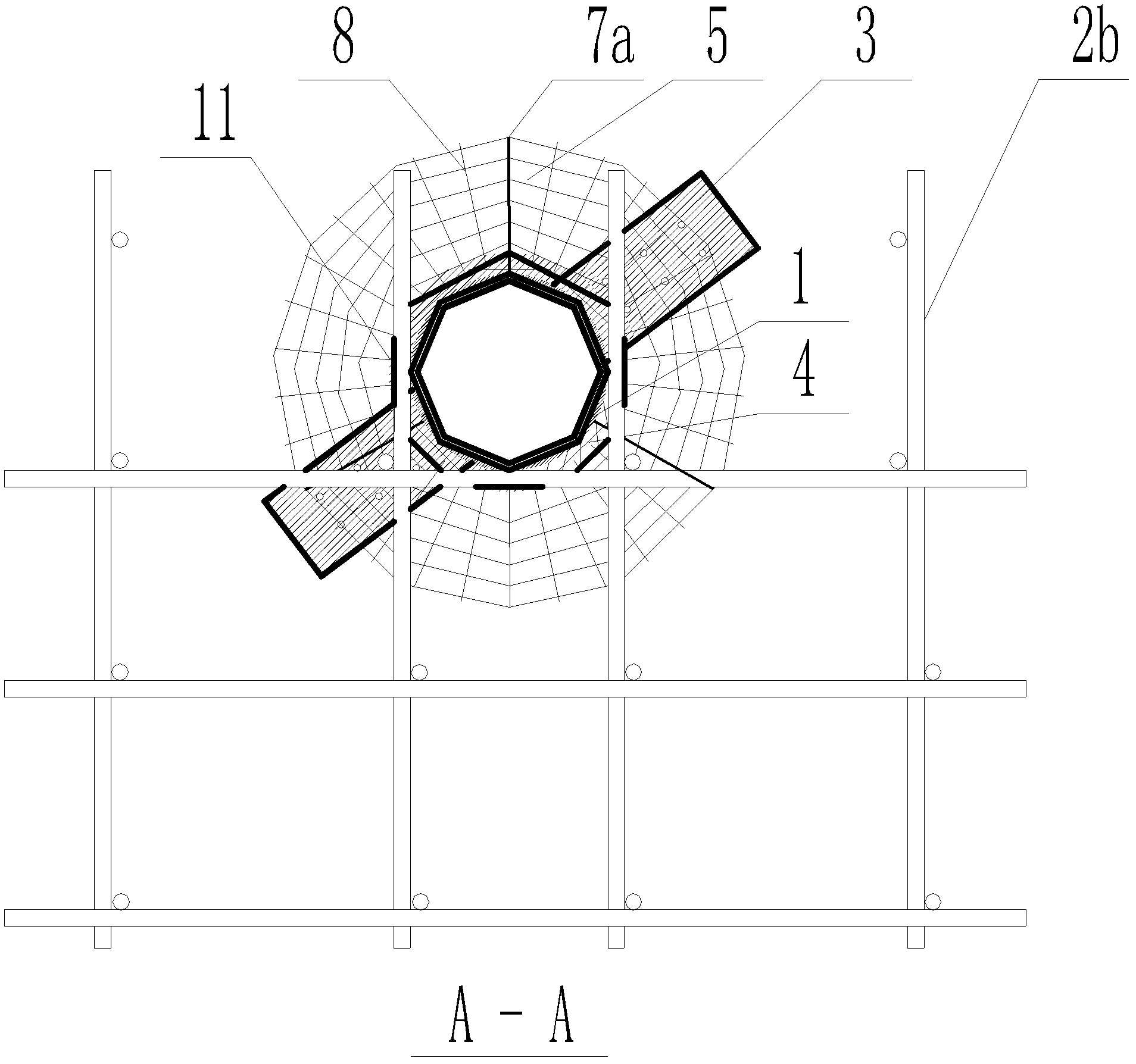
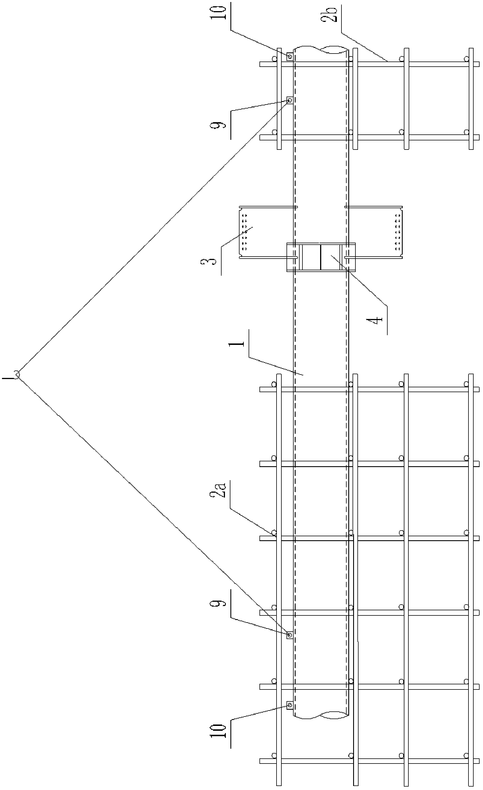
[0043] A steel beam-concrete steel pipe column and a reinforced concrete beam through-the-center connection node construction method, the steps of which are:

[0044] A. Set up a single-layer steel pipe column to support the tire frame and hoist it horizontally on the tire frame:

[0045] Take the single-layer steel pipe column beam-column node as the dividing point to deduct the beam height H of the ring beam steel corbel and the steel beam through-the-heart corbel. At the same time, the diameter D of the single-layer steel pipe column, the diameter D is 600mm ~ 1500mm, and 5mm is added to each side to determine the erection distance of the supporting tire frame vertical poles, plus the length of the span direction of the steel beam through the center of the corbel is the supporting tire frame erecting width , Complete the erection of the front and rear two supporting tire frames.

[0046] According to the position of the upper and lower main bars of the reinforced concrete ...


PUM


Abstract

The invention discloses a construction method of a piercing connection joint between a steel beam / steel pipe concrete column and a reinforced concrete beam. The construction method comprises the steps of: A. building a support jig frame of a monolayer steel pipe column, and hoisting and horizontally putting the monolayer steel pipe column on the jig frame; B. hoisting the monolayer steel pipe column by utilizing inner lifting lugs and sleeving an upper main rib and a lower main rib of an annular reinforced concrete beam on the monolayer steel pipe column; C. lifting the monolayer steel pipe column by using another two lifting ropes and utilizing outer lifting lugs, and dismounting the lifting ropes on the two inner lifting lugs; D. distributing an upper annular main rib and a lower annular main rib to the respective design areas on a circular steel pipe column by employing locating steel bars; E. resetting the monolayer steel pipe column on the support jig frame, and welding the locating steel bars on identifiers of the annular main ribs; F. welding the various annular main ribs to the locating steel bars according to the location of a designed profile by taking the circle center of the circular steel pipe column as a circle center; and G. binding annular reinforced concrete beam stirrups on the fastened annular main ribs. According to the construction method disclosed by the invention, the construction difficulty is reduced; the effect is improved; and the safety and the reliability of the steel pipe column joint can be sufficiently ensured.

Description

technical field [0001] The invention relates to a construction method of a building structure, and in particular to a construction method of a steel beam-concrete steel pipe column and a reinforced concrete beam through-the-center connection node structure. The construction difficulty is reduced and the efficacy is improved. Background technique [0002] As a composite structure that can give full play to and utilize the characteristics of steel and concrete materials and have both advantages in performance, concrete-filled steel tube columns have been widely used in engineering, which improves technical rationality and economic superiority. However, as an important beam-column joint in CFST columns, it has evolved from the relatively simple connection between steel beams and CFST columns or the connection between reinforced concrete beams and CFST columns in the past to a CFST column joint that consists of reinforced concrete beams and ring beams. At the same time, th...

Claims


Application Information

Patent Timeline
Patent Type & Authority Patents(China)
IPC IPC(8): E04G21/12E04G21/14
Inventor 黄昕李文祥江筠
Owner WUHAN CONSTR ENG
Why Eureka
Try Eureka