Control cabin modified gear and engineering machine

A technology of engineering machinery and displacement mechanism, which is applied in the direction of load hanging components, transportation and packaging, etc., can solve the problems of complex hydraulic system and control system, many oil cylinders, and high cost of use, so as to meet the requirements of transportation and operation and reduce the overall cost. The effect of reducing the weight of the machine and reducing the cost of use

Inactive Publication Date: 2012-05-02
SANY AUTOMOBILE HOISTING MACHINERY
View PDF7 Cites 4 Cited by
  • Summary
  • Abstract
  • Description
  • Claims
  • Application Information

AI Technical Summary

Problems solved by technology

[0005] In order to realize the displacement function of the above-mentioned control room, the commonly used technical means in the prior art are: using different independent oil cylinders to realize the pitch displacement and lifting displacement; the pitch displacement and the lifting displacement are controlled by different oil cylinders It satisfies the demand for the displacement of the control room of the crane, but the number of oil cylinders is relatively large, resulting in a more complicated structure of the control room displacement mechanism, more difficult assembly and maintenance, and the weight of the whole machine is relatively large, which is not conducive to the design of the whole machine
[0006] In addition, the more the number of oil cylinders, the more complicated the hydraulic system and control system of the corresponding construction machinery, which increases the difficulty of design and the relatively high cost of use

Method used


Image

  • Control cabin modified gear and engineering machine
  • Control cabin modified gear and engineering machine
  • Control cabin modified gear and engineering machine

Examples


Embodiment Construction

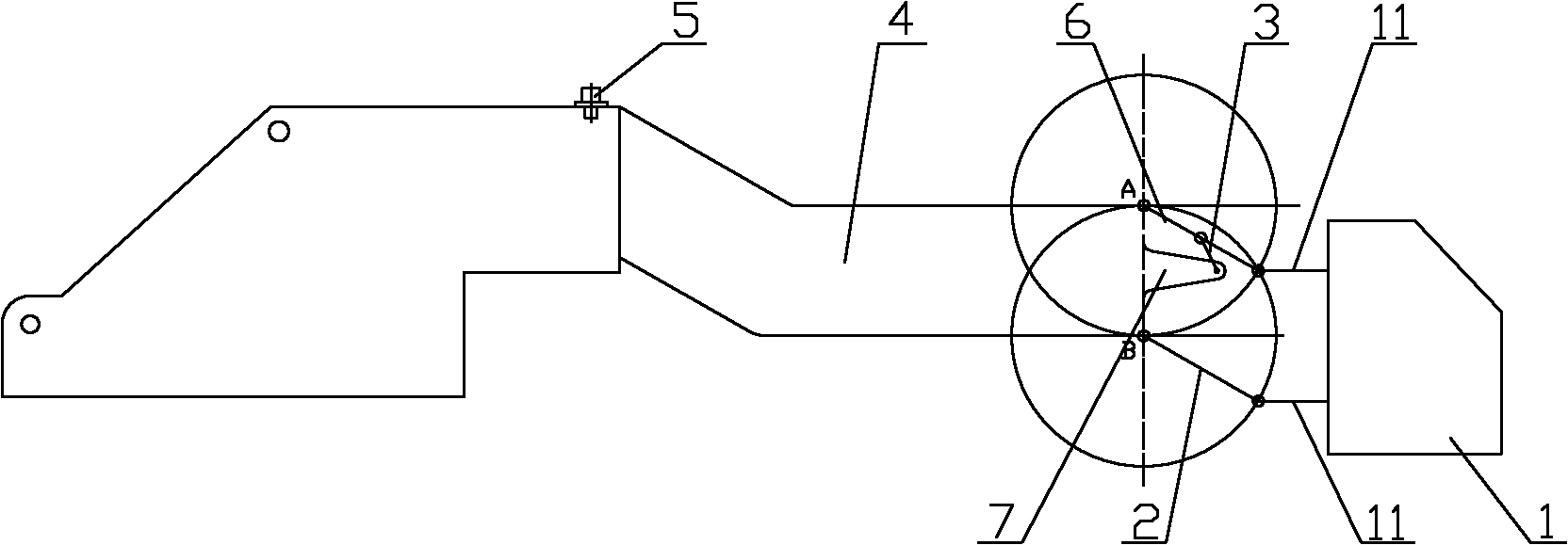
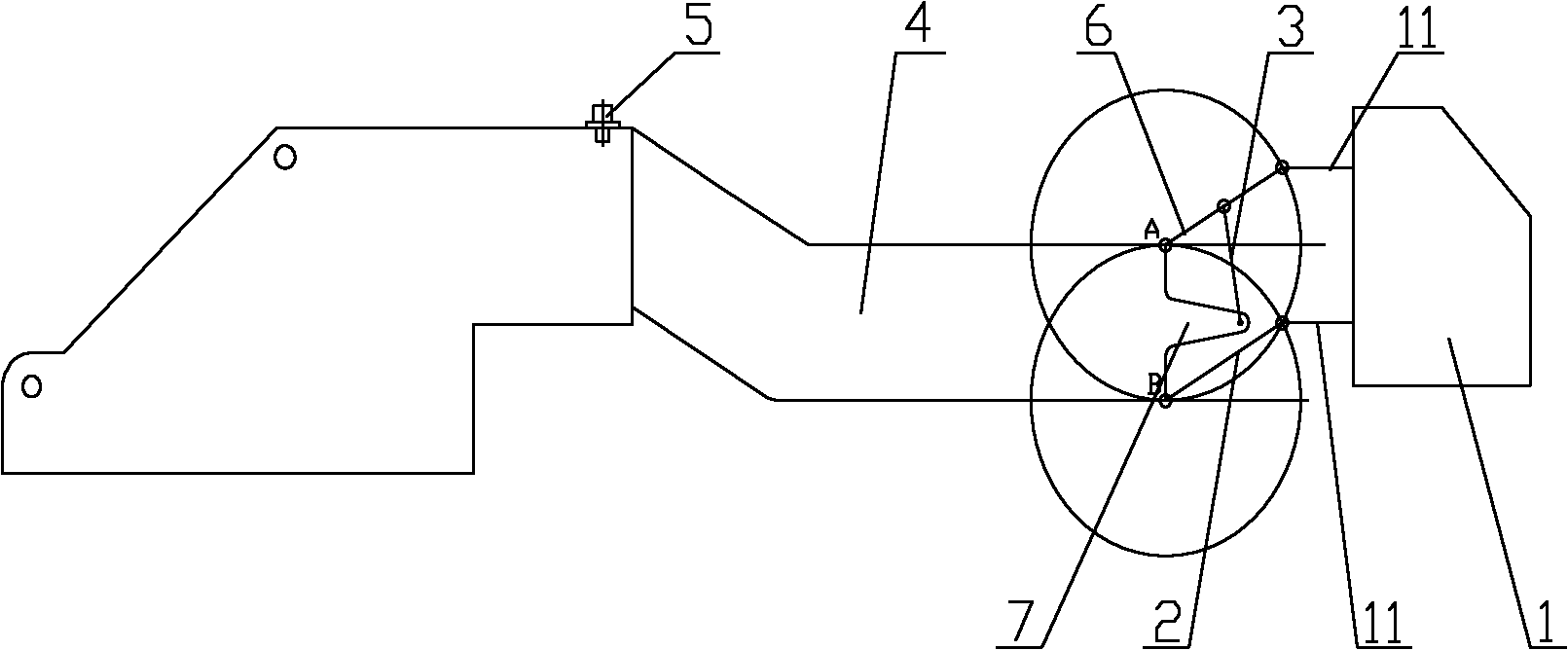
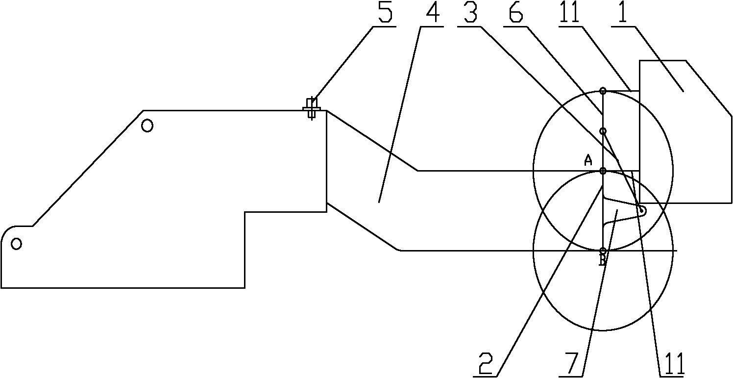
[0027] The core of the present invention is to provide a control room displacement mechanism. On the basis of meeting the working displacement requirements of the control room, the control room displacement mechanism has a relatively simple structure, which is beneficial to reduce the overall weight of the construction machinery, and can simplify The layout of the hydraulic system and control system of construction machinery saves the cost of use. In addition, another core of the present invention is to provide a construction machine including the above-mentioned control room displacement mechanism.

[0028] In order to enable those skilled in the art to better understand the technical solutions of the present invention, the present invention will be further described in detail below in conjunction with the accompanying drawings and specific embodiments.

[0029] Without loss of generality, this article takes an all-terrain crane as an example to introduce the specific working...


PUM


Abstract

The invention discloses a control cabin modified gear of an engineering machine. The control cabin modified gear comprises a control cabin body (1), a rotary rack (4) which is in revolving connection with a rotary table of the engineering machine, a telescopic component (3), a first rod (2) and a limiting mechanism, wherein the telescopic component (3) is used for supporting the control cabin body (1) and driving the control cabin body (1) to move up and down; the two ends of the first rod (2) are hinged between the rotary rack (4) and the control cabin body (1); the limiting mechanism is arranged at a preset position and is used for limiting the rotation of the first rod (2); and under the action of the telescopic component (3), the control cabin body (1) rotates around the hinge point of the control cabin body (1) and the first rod (2) in a vertical plane. The control cabin modified gear disclosed by the invention is simple in structure and is favorable for lightening the weight of a complete machine; and two operations, namely pitching and fluctuating, are completed by only one telescopic component, thus the arrangement of a hydraulic system and an electrical system of the engineering machine can be favorably simplified, and simultaneously, the use cost of the engineering machine can be lowered. The invention also provides the engineering machine comprising the control cabin modified gear.

Description

technical field [0001] The invention relates to the technical field of engineering machinery, in particular to a displacement mechanism for a control room of an engineering machinery. In addition, the present invention also relates to a construction machine comprising the above-mentioned control room displacement mechanism. Background technique [0002] The all-terrain crane is a typical construction machinery. Because of its fast transfer speed and wide application in the lifting environment, it is widely used in the hoisting industry. With the continuous development of wind power, nuclear power and chemical industries, Hoisting operations have higher and higher requirements for the use of all-terrain cranes, and the required tonnage is also increasing. [0003] All-terrain cranes are generally equipped with a control room. In order to meet the requirements of vehicle transportation and operator comfort during hoisting operations, most control rooms have the function of mu...

Claims


Application Information

Patent Timeline
Patent Type & Authority Applications(China)
IPC IPC(8): B66C13/54
Inventor 苏龙黄茂民田伟光
Owner SANY AUTOMOBILE HOISTING MACHINERY
Why Eureka
Try Eureka