Eureka AIR delivers breakthrough ideas for toughest innovation challenges, trusted by R&D personnel around the world.

Transport mechanism

A transmission mechanism and conveyor belt technology, which is applied in the direction of conveyors, conveyor objects, transportation and packaging, etc., can solve the problems of easily damaged tracks, falling, high energy consumption, etc., and achieve energy consumption reduction, precise positioning, and reduction of switches Effect

Active Publication Date: 2012-05-02
DONGGUAN DUOHE AUTOMATION TECH
View PDF7 Cites 7 Cited by
  • Summary
  • Abstract
  • Description
  • Claims
  • Application Information

AI Technical Summary

Problems solved by technology

The two transmission mechanisms mentioned above are more suitable for manual operation, and both have certain defects. The biggest defect is that it is not conducive to multi-station automatic processing, and the energy consumption is relatively large.
[0003] The first transmission mechanism is only suitable for short-distance transmission. If it is used for long-distance transmission, the product will easily be misplaced on the belt, or even fall. This transmission mechanism only has a single transmission function: to transmit the product from the previous station to Manual processing at the next station
The second type of transmission mechanism is not only suitable for manual processing, but also can be applied to machine processing, that is, semi-automatic processing, but the effect is not obvious, because the link between the track shoes is not smooth enough, during the rotation process, there will be a large The vibration and noise; the staff should consider more issues when processing the product on the track: 1. The weight of the product and the quality of the track; 2. The transmission distance. If the transmission distance is too long, it is easy to damage the track; 3. The installation and maintenance of the crawler transmission mechanism

Method used


Image

  • Transport mechanism
  • Transport mechanism
  • Transport mechanism

Examples


Embodiment Construction

[0033] Below in conjunction with accompanying drawing, the present invention is further described:

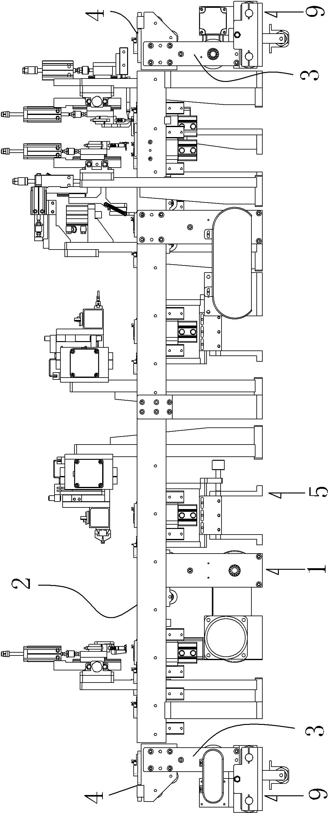
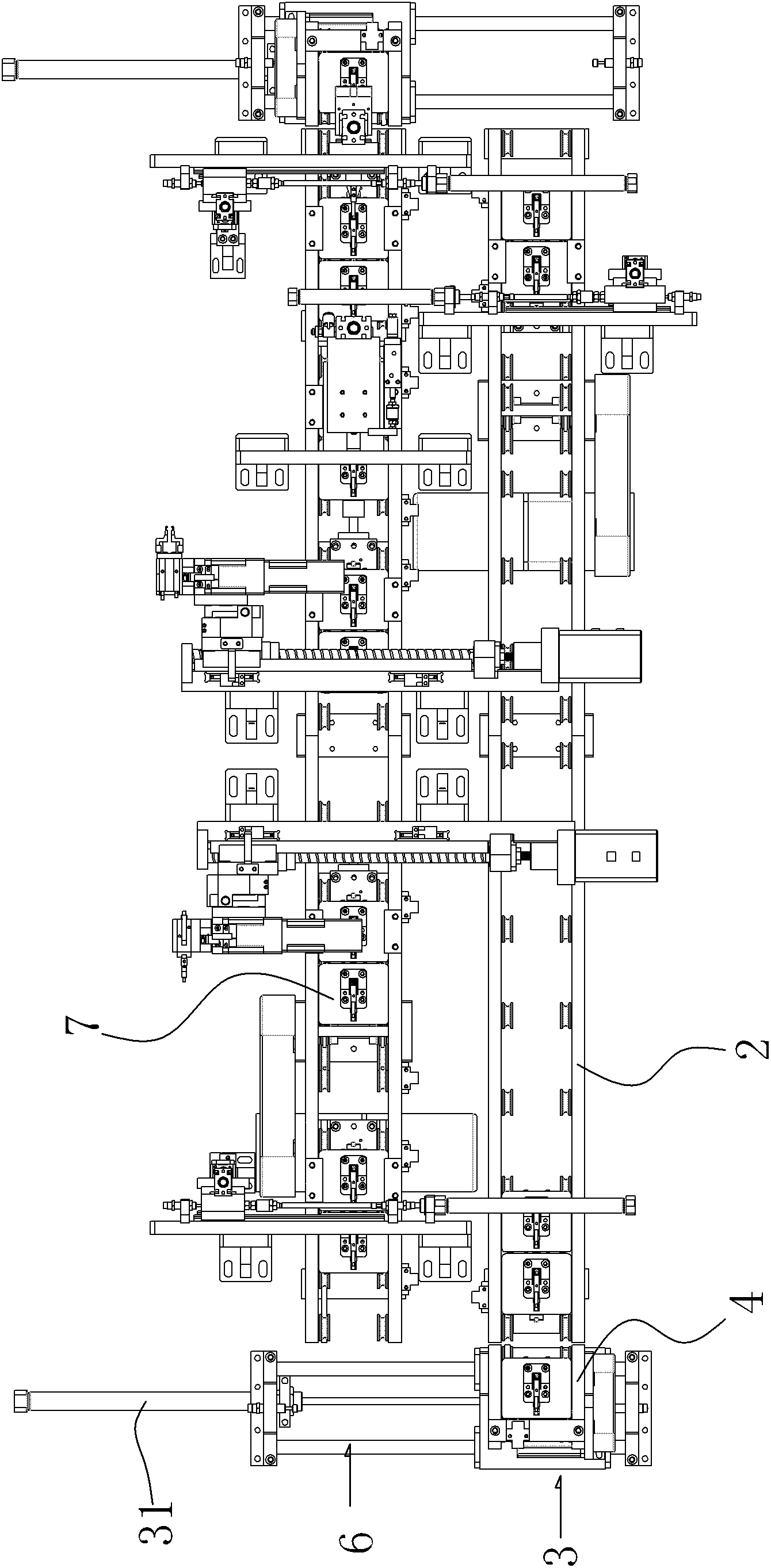
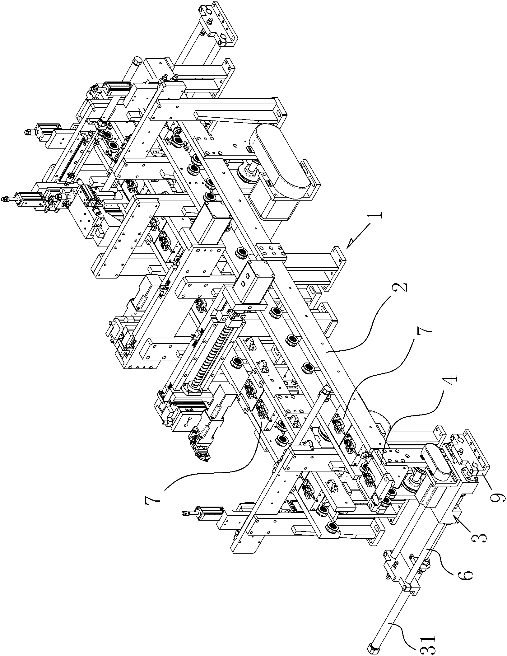
[0034] see Figure 1-8 As shown, the transmission mechanism includes a base frame 1 as a carrier of the present invention, two equal-length, parallel transmission rails 2 are installed on the base frame 1, and a mold base 7 is placed in the transmission rail 2, and the mold base 7 advance along the transmission track 2. Wherein the transmission track 2 adopts a belt drive, that is, a transmission belt is arranged on both sides of the inner wall of the transmission track 2, and the mold base 7 is placed on the belt. When the belt is running, the friction force drives the mold base 7 to run.

[0035] Since the above two transmission tracks 2 are parallel to each other, an engaging mechanism is needed to form a circular transmission track. In the present invention, an engaging mechanism is respectively arranged at both ends of the two transmitting tracks 2, and one of them is con...


PUM


Abstract

The invention discloses a transport mechanism which comprises a base frame, two parallel transporting rails and a die holder, wherein the two parallel transporting rails are installed on the base frame, and the die holder is placed on the transporting rails and is driven by the transporting rails. The transport mechanism also comprises joining mechanisms arranged on two ends of the transporting rails; the die holder on one transporting rail is transferred to the other transporting rail by the joining mechanisms; and the two transporting rails form a circulating transmission rail. The transport mechanism can be suitable for automatically machining on multiple stations, can accurately position and can circularly convey devices.

Description

Technical field: [0001] The invention relates to the field of automatic mechanical processing, in particular to a transmission mechanism suitable for multi-station automatic processing, accurate in positioning, and capable of cyclically conveying components. Background technique: [0002] With the development of modern industry, the transmission mechanism is more and more widely used in the field of mechanical processing. The original transmission mechanism is composed of a motor and a belt. The structure is very simple, but the function is not large, and it only plays a single transmission function. , and it is only suitable for manual processing. Since then, a crawler transmission mechanism has appeared. Because the crawler is relatively hard, the staff can directly process the product on the crawler. The above two transmission mechanisms are relatively suitable for manual operation, and both have certain defects. The biggest defect is that they are not suitable for multi...

Claims


Application Information

Patent Timeline
IPC IPC(8): B65G15/02B65G47/22
Inventor 张福祥
Owner DONGGUAN DUOHE AUTOMATION TECH
Why Eureka
Eureka Blog
Learn More