
Hybrid multilevel current conversion circuit topology structure and control method thereof

A circuit topology and mixed multi-level technology, which is applied in the direction of high-efficiency power electronic conversion, conversion of AC power input to DC power output, electrical components, etc., can solve the problem of high DC bus voltage level, large system loss, and large number of devices, etc. problem, to achieve the effect of reducing system cost, high reliability, and simple connection

Active Publication Date: 2012-04-18
INST OF ELECTRICAL ENG CHINESE ACAD OF SCI
View PDF3 Cites 23 Cited by
  • Summary
  • Abstract
  • Description
  • Claims
  • Application Information

AI Technical Summary

Problems solved by technology

[0003] The purpose of the present invention is to overcome the disadvantages of high DC bus voltage level, large number of components, large system loss, complicated control and high system cost required by the existing converter topology. Based on hybrid multi-level technology, a three-phase adjustable Shared DC bus, new high-voltage and high-power converter topology suitable for back-to-back structure and its control method

Method used


Image

  • Hybrid multilevel current conversion circuit topology structure and control method thereof
  • Hybrid multilevel current conversion circuit topology structure and control method thereof
  • Hybrid multilevel current conversion circuit topology structure and control method thereof

Examples


Embodiment Construction

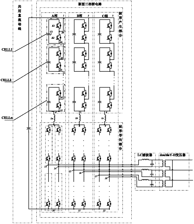
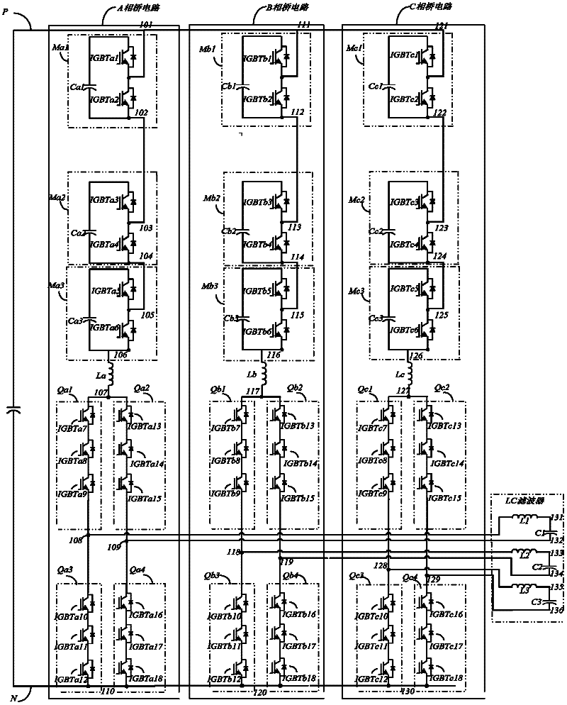
[0038] Such as figure 1 As shown, the present invention includes: three-phase shared positive DC bus, three-phase shared negative DC bus and A-phase bridge circuit, B-phase bridge circuit, C-phase bridge circuit, A-phase LC filter circuit, B-phase LC filter circuit, C-phase LC filter circuit, doubleY-Δ transformer. The first lead-out terminal 1 of the A-phase bridge circuit, the first lead-out terminal 2 of the B-phase bridge circuit, and the first lead-out terminal 3 of the C-phase bridge circuit are connected to the positive DC bus. The second lead-out terminal 10 of the A-phase bridge circuit, the second lead-out terminal 11 of the B-phase bridge circuit, and the second lead-out terminal 12 of the C-phase bridge circuit are connected to the negative DC bus. The third lead-out terminal 13 and the fourth lead-out terminal 14 of the A-phase bridge circuit are connected to the input end of the A-phase filter circuit, the third lead-out terminal 15 and the fourth lead-out termi...


PUM


Abstract

The invention discloses a hybrid multilevel current conversion circuit topology structure, which comprises a direct current bus shared by three phases, an A-phase bridge circuit, a B-phase bridge circuit, a C-phase bridge circuit, an A-phase LC filtering circuit, a B-phase LC filtering circuit and a C-phase LC filtering circuit, wherein a first leading-out terminal of the A-phase bridge circuit, a first leading-out terminal of the B-phase bridge circuit and a first leading-out terminal of the C-phase bridge circuit are connected with a positive direct current bus; a second leading-out terminal of the A-phase bridge circuit, a second leading-out terminal of the B-phase bridge circuit and a second leading-out terminal of the C-phase bridge circuit are connected with a negative direct current bus; third and fourth leading-out terminals of the A-phase bridge circuit are connected with the A-phase LC filtering circuit; third and fourth leading-out terminals of the B-phase bridge circuit are connected with the B-phase LC filtering circuit; and third and fourth leading-out terminals of the C-phase bridge circuit are connected with the C-phase LC filtering circuit. The hybrid multilevel current conversion circuit topology structure can be applied to back-to-back structures and high voltage direct current transmission (HVDC) and flexible alternating current transmission systems (FACTS).

Description

technical field [0001] The invention relates to an AC-DC conversion circuit topology and a control method thereof, in particular to a hybrid multilevel converter circuit topology and a control method for providing three-phase AC and DC conversion for high-voltage and high-power applications. Background technique [0002] The research on high-voltage and high-power commutation technology began in the 1970s, and serial-parallel technology of power devices, inverter parallel technology, transformer multiplexing technology, and combined inverter phase-shift SPWM technology appeared successively. Although these technologies have improved The voltage and power levels of the commutation technology, but most of them have not reached the level of customer satisfaction in terms of output voltage waveform quality, reliability, and loss. Multi-level converter circuit topology technology is a new type of inverter that achieves high-voltage and high-power output by improving the topology ...

Claims


Application Information

Patent Timeline
IPC IPC(8): H02M7/00H02M1/08
CPCH02M7/7575Y02B70/10Y02E60/60H02M1/0058H02M7/4835H02M1/0095
Inventor 朱晋韦统振霍群海
Owner INST OF ELECTRICAL ENG CHINESE ACAD OF SCI
Learn More