
Circuit for improving multi-path output cross regulation rate of switching power supply

A cross-regulation rate and multi-output technology, which is applied in the direction of output power conversion device, DC power input conversion to DC power output, electrical components, etc., can solve the problems of complexity, difficult application of circuits, high cost, etc., and achieve low cost , The circuit performance is reliable and practical, and the effect of high precision

Inactive Publication Date: 2012-04-18
NANJING APAITEK TECH
View PDF4 Cites 7 Cited by
  • Summary
  • Abstract
  • Description
  • Claims
  • Application Information

AI Technical Summary

Problems solved by technology

There are many types of existing circuits for improving output cross-regulation, which are either complex or only theoretically meaningful, and are difficult to apply in actual circuits, and the cost is relatively expensive

Method used


Image

  • Circuit for improving multi-path output cross regulation rate of switching power supply
  • Circuit for improving multi-path output cross regulation rate of switching power supply

Examples


Embodiment Construction

[0014] Below in conjunction with accompanying drawing, technical content of the present invention is described:

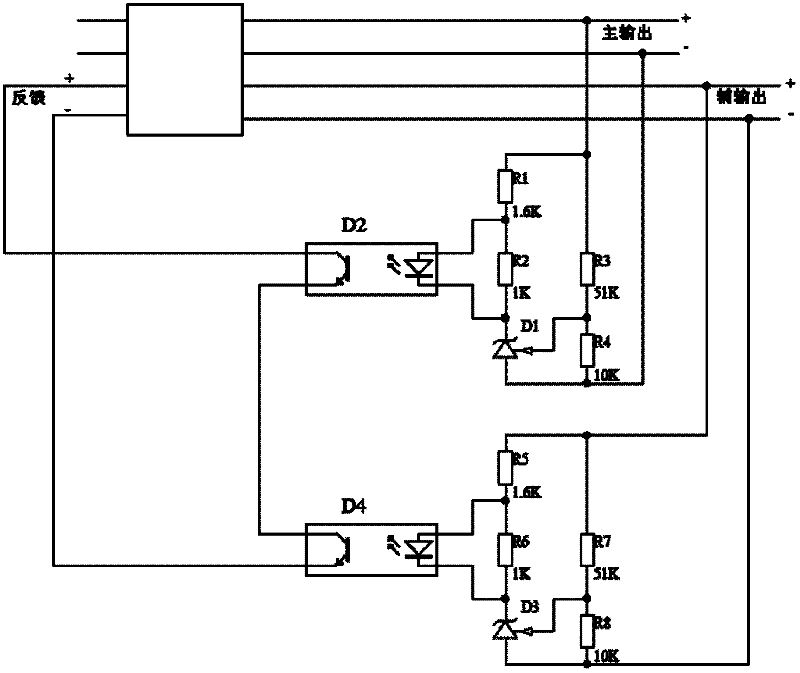
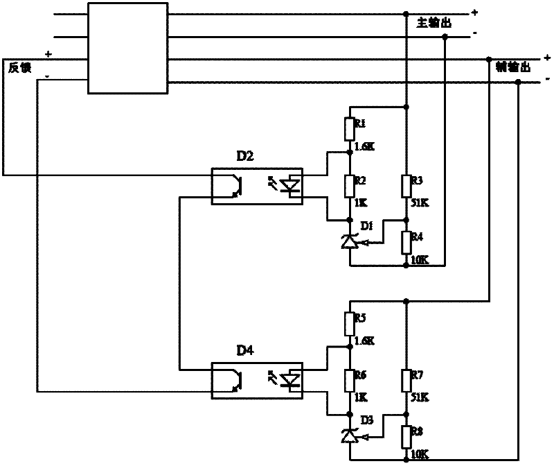
[0015] Such as figure 1 As shown, the improved switching power supply multi-channel output cross regulation rate circuit of the present invention includes two optocouplers, optocoupler D2 and optocoupler D4, resistor R1, resistor R2, resistor R3, resistor R4, resistor R5, resistor R6, resistor R7, Resistor R8 has a total of 8 resistors and 2 three-terminal adjustable shunt reference sources D1 and D3. One end of resistor R1 is connected to the positive pole of the main output and one end of resistor R3, and the other end of resistor R1 is connected to one end of resistor R2 and the optocoupler D2. The input ends of the light-emitting diodes are connected together, the other end of the resistor R2 is connected with the output end of the light-reflecting diode of the optocoupler D2 and the cathode of the three-terminal adjustable shunt reference source D1, and the an...


PUM


Abstract

The invention discloses a circuit for improving the multi-path output cross regulation rate of a switching power supply. The circuit has reliable and practical performance and low cost, is particularly suitable for places with low cost requirements and well improves the multi-path output cross regulation rate; and the output of each path is highly accurate. The circuit for improving the multi-path output cross regulation rate of the switching power supply comprises optocouplers D2 and D4, resistors R1, R2, R3, R4, R5, R6, R7 and R8 and three-end adjustable shunt reference sources D1 and D3.

Description

technical field [0001] The invention relates to a circuit, more specifically to a circuit for improving the multi-channel output cross regulation rate of a switching power supply, which belongs to the field of power electronics. Background technique [0002] The switching power supply with multiple outputs is widely used in the power supply of various power electronic systems. For the case of multiple outputs, the one with lower output voltage and larger current variation range is usually used as the main output circuit, and feedback adjustment control is performed on it to ensure stable voltage output when the input voltage and load change. Ideally, the auxiliary output voltage and the main output voltage satisfy the relationship of transformer turns ratio, that is, as long as the main output voltage is kept stable, the auxiliary output voltage can also be kept stable. But in fact, due to the influence of the leakage inductance between the windings of the transformer, the ...

Claims


Application Information

Patent Timeline
Patent Type & Authority Applications(China)
IPC IPC(8): H02M3/156
Inventor 花跃学
Owner NANJING APAITEK TECH
Learn More