Self-recovery stop type protection circuit for low-voltage and high-power safety barrier

A technology for protecting circuits and power switching circuits, applied in the direction of protection against overcurrent, etc., can solve the problems of safety hazards, monitoring and monitoring systems that are not widely used, and achieve low power loss, novel and reasonable design, and low power loss Effect

Active Publication Date: 2012-04-18
XIAN UNIV OF SCI & TECH
View PDF4 Cites 14 Cited by
  • Summary
  • Abstract
  • Description
  • Claims
  • Application Information

AI Technical Summary

Problems solved by technology

According to statistics, there are currently about 26,000 coal mines of various types in my country, including more than 3,000 large and medium-sized coal mines. The key problem is that monitoring and monitoring systems are not widely used, and there are many potential safety hazards. An intrinsically safe switching power supply, equipment improvement is imminent

Method used


Image

  • Self-recovery stop type protection circuit for low-voltage and high-power safety barrier
  • Self-recovery stop type protection circuit for low-voltage and high-power safety barrier
  • Self-recovery stop type protection circuit for low-voltage and high-power safety barrier

Examples


Embodiment 1

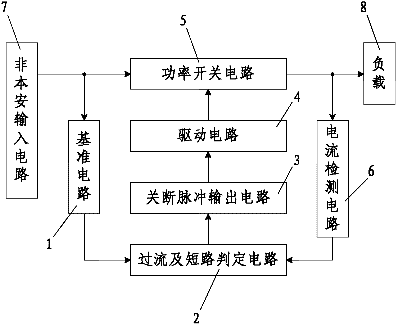
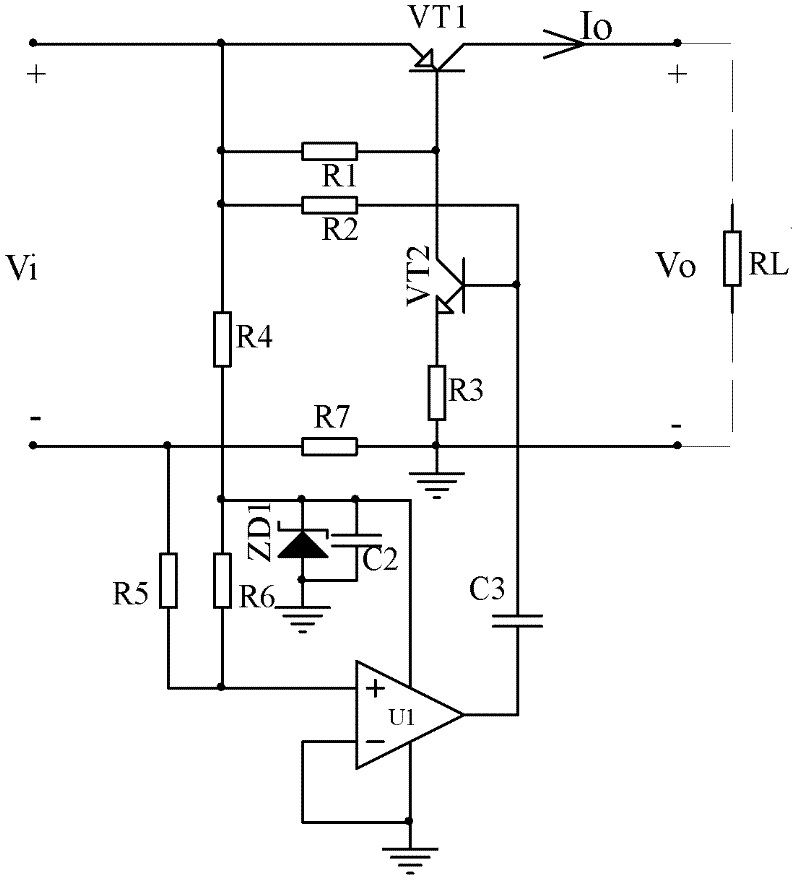
[0034] Such as figure 1 As shown, the present invention is connected between the non-intrinsically safe input circuit 7 and the load 8, including the power switch circuit 5 connected between the non-intrinsically safe input circuit 7 and the load 8 and used to control the opening or closing of the circuit, and the power switch The circuit 5 is connected with the current detection circuit 6 used for real-time detection of the magnitude of the current in the circuit, the overcurrent and short circuit judgment circuit 2 connected with the current detection circuit 6 and used for judging whether an overcurrent or short circuit occurs, and the overcurrent and short circuit The judgment circuit 2 is connected and used to output the shutdown pulse output circuit 3 when the overcurrent or short circuit occurs, and the shutdown pulse output circuit 3 is connected to the shutdown pulse output circuit 3 and is used to control the drive of the power switch circuit 5 to turn off or open. C...

Embodiment 2

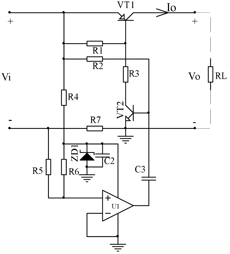
[0042] combine image 3 The difference between this embodiment and Embodiment 1 is that the emitter of the NPN transistor VT2 is grounded, the collector of the NPN transistor VT2 is connected to one end of the resistor R3, and the other end of the resistor R3 is a drive circuit 4 output terminals. The rest of the circuit structure is the same as that of Embodiment 1.

Embodiment 3

[0044] combine Figure 4 The difference between this embodiment and Embodiment 1 is that the power switch circuit 5 includes a resistor R1 and an enhanced PMOS transistor VT3, and one end of the resistor R1 and the source of the enhanced PMOS transistor VT3 are connected to the non-intrinsically safe input circuit The positive output end of 7 is connected, the other end of the resistor R1 is connected to the gate of the enhanced PMOS transistor VT3 and connected to the output end of the drive circuit 4, and the drain of the enhanced PMOS transistor VT3 is a power switch circuit The positive output terminal of 5 is connected with the positive pole of the load 8. The rest of the circuit structure is the same as that of Embodiment 1.


PUM


Abstract

The invention discloses a self-recovery stop type protection circuit for a low-voltage and high-power safety barrier. The self-recovery stop type protection circuit comprises a power switching circuit which is connected between a non intrinsic safety input circuit and a load and used for controlling switch-on and switch-off of a circuit, a current detection circuit which is connected with the power switching circuit and used for detecting current in the circuit in real time, an overcurent and shortcircuit judgment circuit which is connected with the current detection circuit, a switch-off pulse output circuit which is connected with the overcurent and shortcircuit judgment circuit, and a driving circuit which is connected with the switch-off pulse output circuit, wherein the input end of the overcurent and shortcircuit judgment circuit is connected with a reference circuit; the reference circuit is connected with the non intrinsic safety input circuit; and the driving circuit comprises an oscillation circuit for making the power switching circuit automatically re-switch on after the power switching circuit is switched off. The self-recovery stop type protection circuit has a simple structure, low power loss, high output power, a wide application range and high popularization and application value; the normal transmission of high-power electric energy is not influenced; and a requirement for intrinsic safety output is met.

Description

technical field [0001] The invention relates to an electronic product, in particular to a self-restoring cut-off protection circuit of a low-voltage high-power safety barrier connected between a non-intrinsically safe output power supply in a safe environment or an electronic product and an intrinsically safe device in a hazardous environment . Background technique [0002] When a non-intrinsically safe circuit is connected to an intrinsically safe circuit working in a dangerous environment such as coal mines and petrochemicals, the output voltage, current and other signals may be very large, which exceeds the scope of intrinsic safety. If it is directly connected to the intrinsically safe circuit , The spark caused by the fault may detonate the flammable and explosive gas or mixture in the hazardous environment. Therefore, in order for the non-intrinsically safe circuit to be safely applied in a hazardous environment, it is necessary to introduce a high-power safety barrie...

Claims


Application Information

Patent Timeline
IPC IPC(8): H02H3/08
Inventor 刘树林杨波王媛媛张兴平文美娟
Owner XIAN UNIV OF SCI & TECH
Why Eureka
Try Eureka