
Support control device for hydraulic support

A technology of hydraulic supports and control devices, which is applied in mine roof supports, mining equipment, earthwork drilling and mining, etc. It can solve the problems of poor matching of resources, heavy workload of cable connectors, idleness, etc., and improve the utilization of resources Efficiency and convenient system maintenance

Active Publication Date: 2014-02-19
BEIJING TIANMA INTELLIGENT CONTROL TECH CO LTD
View PDF8 Cites 0 Cited by
  • Summary
  • Abstract
  • Description
  • Claims
  • Application Information

AI Technical Summary

Problems solved by technology

[0002] The hydraulic support is an important equipment for underground mining. The use of the support electro-hydraulic control system can reduce the labor intensity of the operator, improve the production efficiency of the coal mine, and realize the unmanned mining of the coal mine. With continuous improvement, the support control system needs to detect multiple sensing elements of equipment status information and a variety of different quantities. However, the current support control devices all use a fixed mode and a fixed number of electrical interfaces. The automation requirements for different types of working surfaces , the resources of the bracket control device cannot be well matched, some functions cannot be satisfied, but some resource functions are idle, resulting in waste of resources and increased equipment costs
When performing equipment maintenance on the downhole support control device, due to the narrow installation space, the support control device has multiple cable connectors installed on the mounting frame through the mounting plate, and the workload of pulling and inserting the cable connectors one by one is large, and equipment maintenance is relatively difficult.

Method used


Image

  • Support control device for hydraulic support
  • Support control device for hydraulic support
  • Support control device for hydraulic support

Examples


Embodiment Construction

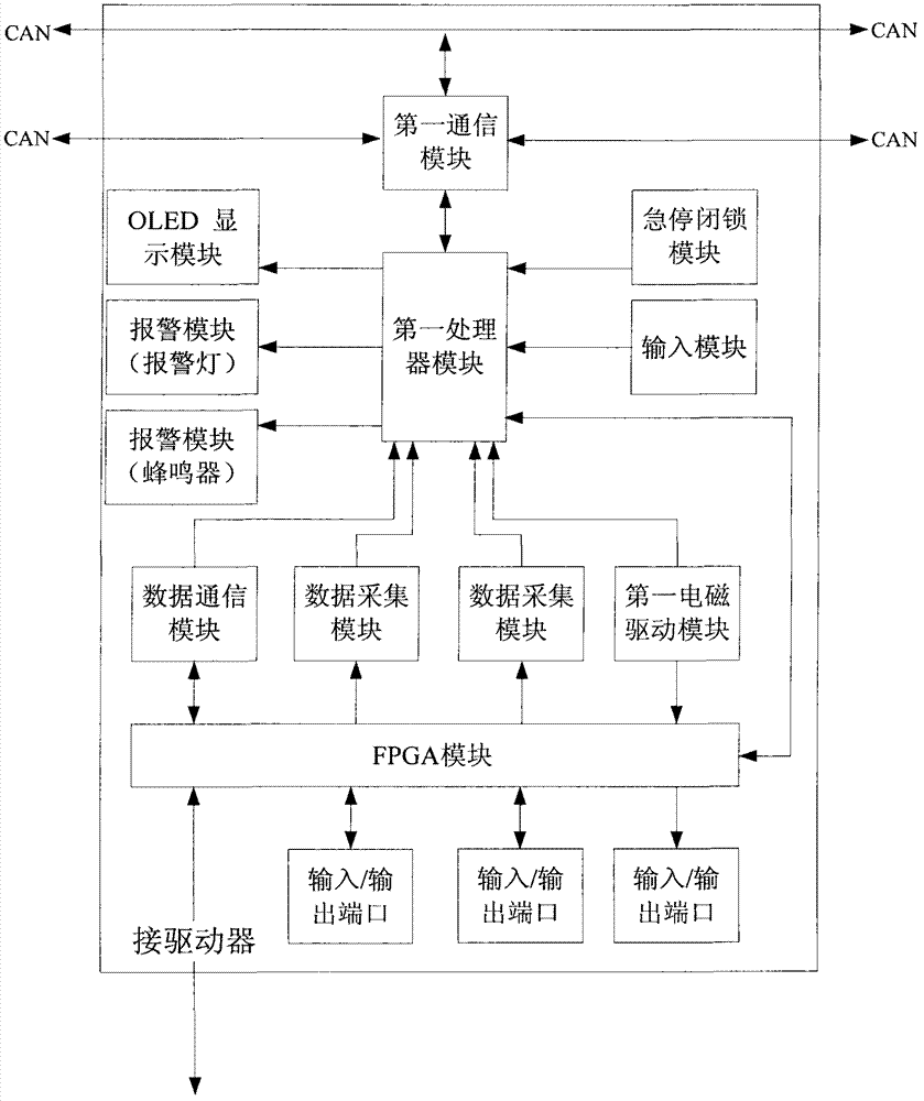
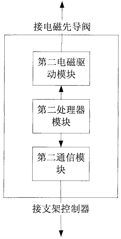
[0027] See attached figure 1 , a support control device, including a support controller and a driver, the support controller is installed on the hydraulic support, the support controller includes a processor module, a communication module, an input module, a data acquisition module, an OLED display module, an alarm Module, data communication module, emergency stop locking module and FPGA module, described communication module, input module, data acquisition module, OLED display module, alarm module, data communication module, emergency stop locking module and FPGA module are connected with processor module respectively ; The communication module includes three-way CAN buses, two of which are connected to the support controllers of the left and right adjacent hydraulic supports for data communication between adjacent support controllers, and the other CAN bus is connected to the CAN bus on the working surface. The CAN bus of the working surface is a bus that runs through the wo...


PUM


Abstract

The invention relates to a support control device for a hydraulic support. The device comprises a support controller and a driver, wherein the support controller is arranged on the hydraulic support and comprises a first processor module, a first communication module, an input module, a data acquisition module, a first electromagnetic driving module, an organic light emitting diode (OLED) display module, an alarm module, a data communication module, an emergency stop locking module and a field programmable gate array (FPGA) module; and the driver comprises a second processor module, a second electromagnetic driving module and a second communication module. The support control device can meet different working surface automatic application requirements through function matching, and the resource utilization rate of the support control device is improved; the support controller can be independently used to meet the action control requirement of a 16-function support, and also can be matched with the driver to meet the action control requirement of a 26-function support; and a cable connector can be integrally inserted and extracted by the support controller through a connecting block, and equipment replacement and system maintenance are facilitated.

Description

technical field [0001] The invention relates to an electronic device for controlling the action of a hydraulic support and communicating with other hydraulic supports, in particular to a support control device for a hydraulic support on a fully mechanized mining face under a coal mine. Background technique [0002] The hydraulic support is an important equipment for underground mining. The use of the support electro-hydraulic control system can reduce the labor intensity of the operator, improve the production efficiency of the coal mine, and realize the unmanned mining of the coal mine. With continuous improvement, the support control system needs to detect multiple sensing elements of equipment status information and a variety of different quantities. However, the current support control devices all use a fixed mode and a fixed number of electrical interfaces. The automation requirements for different types of working surfaces , The resources of the bracket control device ...

Claims


Application Information

Patent Timeline
Patent Type & Authority Patents(China)
IPC IPC(8): E21D23/12
Inventor 李首滨姜文峰牛剑峰代刚
Owner BEIJING TIANMA INTELLIGENT CONTROL TECH CO LTD
Learn More