Hairiness reducing device and yarn winding device
A winding device, yarn technology, applied in the direction of transportation and packaging, textiles and papermaking, conveying filamentous materials, etc., can solve problems such as insufficient response
- Summary
- Abstract
- Description
- Claims
- Application Information
AI Technical Summary
Problems solved by technology
Method used
Image


Examples
Embodiment 1
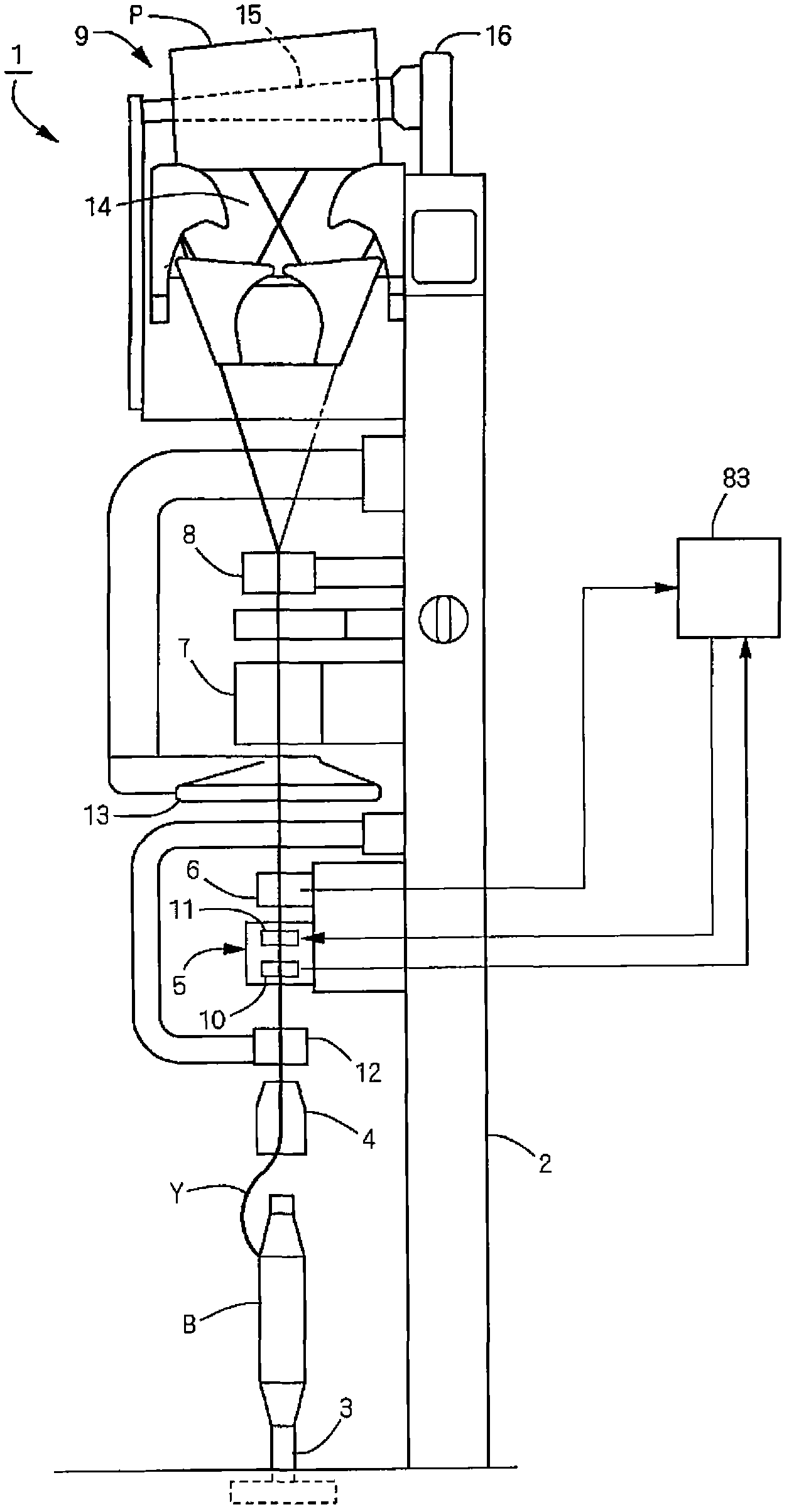
[0041] (Example 1) figure 1 and even Figure 7 Embodiment 1 of the yarn winding device (automatic winder) according to the present invention is shown. Such as figure 1 As shown, the yarn winding device 1 has a vertically long box-shaped main body frame 2 . On the left side of the main body frame 2, along the yarn traveling path of the yarn Y extending from below to above, a bobbin supporting section 3, an unwinding assisting device 4, a tension applying section 5, a tension sensor 6, and a yarn Y are disposed. A yarn splicing device 7, a slub catcher 8, a winding unit 9, and the like form a package P capable of winding the yarn Y of the yarn supplying bobbin B supported by the bobbin supporting unit 3. Among them, in addition to the tension device 10, the tension imparting unit 5 is provided with a fluff removing device 11 which is a characteristic part of the present invention.
[0042] The unwinding assisting device 4 suppresses an increase in unwinding tension due to a ...
Embodiment 2
[0067] (Example 2) Figure 8 (a) and (b) show a pair of pressing bodies 85 and 86 concerning Example 2 of this invention. Each of the pressing bodies 85, 86 has a circular plate-shaped portion when viewed from the opposing surface side (the side in contact with the yarn), and the plate-shaped portion of one of the pressing bodies 85 is a first plate. The member 87 and the plate-shaped portion of the other pressing body 86 serve as a second plate member 88 . In addition, pressing portions (pressing members) 89 , 90 are formed in annular shapes and positioned to face each other along the peripheral edges of the faces facing each other. Yarn contact portions 91 , 92 that come into contact with the yarn to press the yarn are formed on the opposing surface sides of the pressing portions 89 , 90 . Each of the yarn contact portions 91, 92 is constituted by a convex portion having an arc-shaped cross-sectional shape after cutting the pressing bodies 85, 86 in the radial direction. ...
Embodiment 3
[0069] (Example 3) Figure 9 (a) and (b) show a pair of pressing bodies 93 and 94 concerning Example 3 of this invention. In this third embodiment, one of the pair of pressing bodies 93, 94 has a pressing body 93 having the same structure as the pressing body 85 of the second embodiment, so corresponding parts are given the same reference numerals and descriptions thereof are omitted. The structure of one pressing body 94 is different from that of the second embodiment. That is, although the other pressing body 94 of this Example 3 has the pressing portion (second pressing member) 95 sandwiching the yarn traveling path, the yarn contact portion (second yarn contacting portion) formed on the pressing portion 95 Section) 96 is the plane along the path of yarn travel. Specifically, the end face of the pressing portion (second pressing member) 95 sandwiching the yarn traveling path on the side of the yarn contacting portion 96 is chamfered in an arc shape, and the area surrounde...
PUM
 Abstract
Description
Claims
Application Information
 - Generate Ideas
- Intellectual Property
- Life Sciences
- Materials
- Tech Scout
- Unparalleled Data Quality
- Higher Quality Content
- 60% Fewer Hallucinations
Browse by: Latest US Patents, China's latest patents, Technical Efficacy Thesaurus, Application Domain, Technology Topic, Popular Technical Reports.
© 2025 PatSnap. All rights reserved.Legal|Privacy policy|Modern Slavery Act Transparency Statement|Sitemap|About US| Contact US: help@patsnap.com