
Pressing mold for manufacturing amplitude/multi-polar oriented whole permanent magnetic ring

A technology for pressing molds and permanent magnetic rings, which is applied in the manufacture of inductors/transformers/magnets, electrical components, circuits, etc., and can solve problems such as complex magnetic structure, inconvenient installation, single-orientation orientation or multi-pole orientation magnetic field, etc. Achieve the effect of simplifying the magnetic conduction structure, convenient installation and excellent magnetic performance

Inactive Publication Date: 2012-04-18
湖南航天有限责任公司
View PDF8 Cites 12 Cited by
  • Summary
  • Abstract
  • Description
  • Claims
  • Application Information

AI Technical Summary

Problems solved by technology

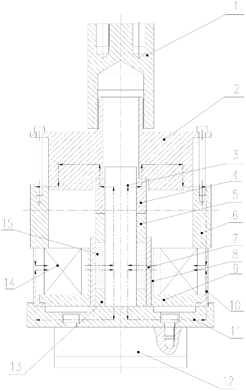
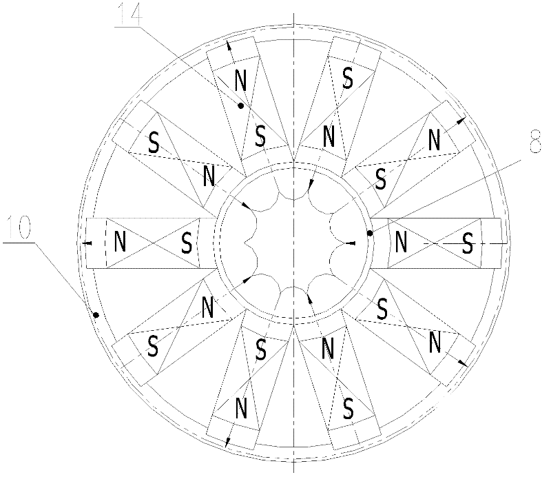
[0004] In order to overcome the defect that the existing magnetic structure is complicated, installation is inconvenient, and it can only produce a single orientation orientation or a multi-pole orientation magnetic field, the present invention aims to provide a pressing mold for preparing an integral permanent magnet ring with an amplitude orientation or multi-pole orientation, When the electromagnets constituting the electromagnet ring are supplied with current in the same direction, the pressing mold will form an orientation magnetic field; Realize the production of integral permanent magnet rings in the width direction or multi-pole orientation

Method used


Image

  • Pressing mold for manufacturing amplitude/multi-polar oriented whole permanent magnetic ring
  • Pressing mold for manufacturing amplitude/multi-polar oriented whole permanent magnetic ring
  • Pressing mold for manufacturing amplitude/multi-polar oriented whole permanent magnetic ring

Examples


Embodiment Construction

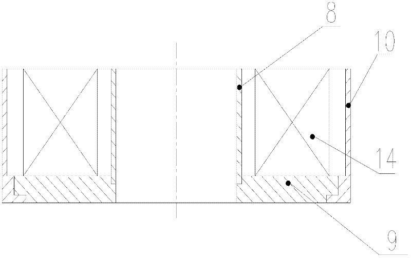
[0030] see figure 1 , figure 2 and image 3 , the pressing mold of the radial or multi-pole oriented integral permanent magnet ring according to the present invention includes a pressing part and a part for generating a radial or multi-polar oriented magnetic field. There is enough clearance between the pressing upper ram 2 and the core rod 3, the magnetically permeable upper die 4 and the non-magnetically permeable upper die 5, which is convenient for adjustment when installing the mould. There are through holes around the upper end of the pressing upper head 2, and the bolts are fixed to press the upper sleeve 6. Through the through holes, the pressing upper pressing head 2 is covered with an upper sleeve 6, and the pressing upper pressing head 2 can be opposite to the upper sleeve. 6 moves up and down to ensure that during the pressing process, the pressing upper sleeve 6 and the pressing upper head 2 are always in contact. The upper end surface of the female mold 7 is ...


PUM


Abstract

The invention relates to a pressing mold for manufacturing an amplitude / multi-polar oriented whole permanent magnetic ring. The pressing mold comprises a core rod arranged on a lower bearing plate, and a lower mold, a non magnetic conducting upper mold and a magnetic conducting upper mold which are sleeved on the core rod from bottom to top in turn, wherein a pressing upper pressure head for making the magnetic conducting upper mold slide along the core rod is arranged on the top of the magnetic conducting upper mold; a female mold is sleeved outside the lower mold and the non magnetic conducting upper mold; a pressing cavity for accommodating magnetic powder is formed among the female mold, the lower mold, the non magnetic conducting upper mold and the core rod; and an electromagnetic iron ring for providing a magnetic field is sleeved outside the female mold. Permanent magnetic powder with magnetocrystalline anisotropy is put into a forming mold and is formed under the action of an amplitude / multi-polar oriented magnetic field and a pressure field, and the whole permanent magnetic ring with amplitude / multi-polar oriented texture characteristics is obtained. The amplitude / multi-polar oriented magnetic ring is produced by the same set of mold, and the manufactured whole permanent magnetic ring has the characteristics of uniform density and orientation degree, high consistency, uniform surface magnetic field and high magnetic property.

Description

technical field [0001] The invention belongs to the technical field of permanent magnet material preparation, and in particular relates to a pressing mold for preparing an integral permanent magnet ring with width or multi-pole orientation. Background technique [0002] With the development of science and technology, the requirements for the shape, size and precision of permanent magnet products are getting higher and higher. Radial or multi-pole orientation magnetic rings are mainly used in motors, multi-injection speed tubes, inertial navigation gyros, accelerometers, The gyroscope permanent magnet torquer and other high-precision devices used in the tank aiming system, aviation, navigation and other fields, the radial or multi-pole orientation magnetic ring is spliced ​​by multiple parallel or radial orientation magnets in the actual process It is called "false" radial or multi-pole orientation magnetic ring. The magnetic field distribution on the surface of the radial or...

Claims


Application Information

Patent Timeline
Patent Type & Authority Applications(China)
IPC IPC(8): B22F3/03H01F41/02
Inventor 谭春林罗明李彬胡娟万绍平文晓林
Owner 湖南航天有限责任公司
Learn More