Electric motor, and motor with a reduction gear
An electric motor and armature technology, which is applied in the field of electric motors, can solve the problems of large changes in magnetic flux, reduce the changes in magnetic attraction and repulsion, ensure the space of the package, and increase the number of turns of the package.
- Summary
- Abstract
- Description
- Claims
- Application Information
AI Technical Summary
Problems solved by technology
Method used
Image
Examples
no. 1 approach
[0068] (motor with reducer)
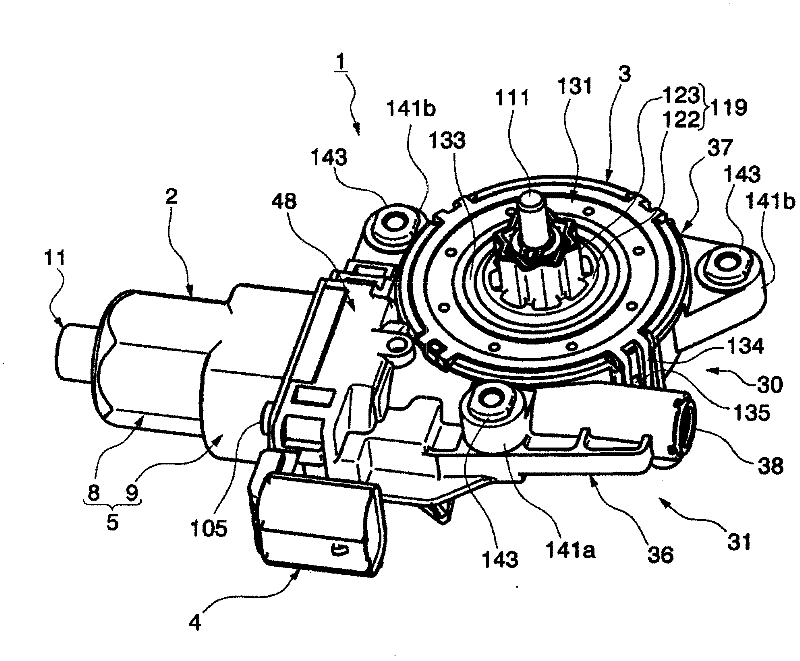
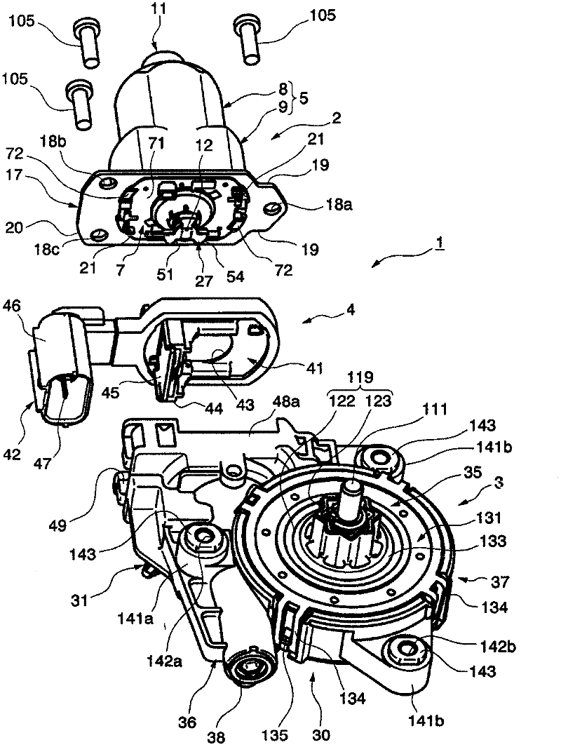
[0069] Next, based on Figure 1 to Figure 6 A first embodiment of the present invention will be described.
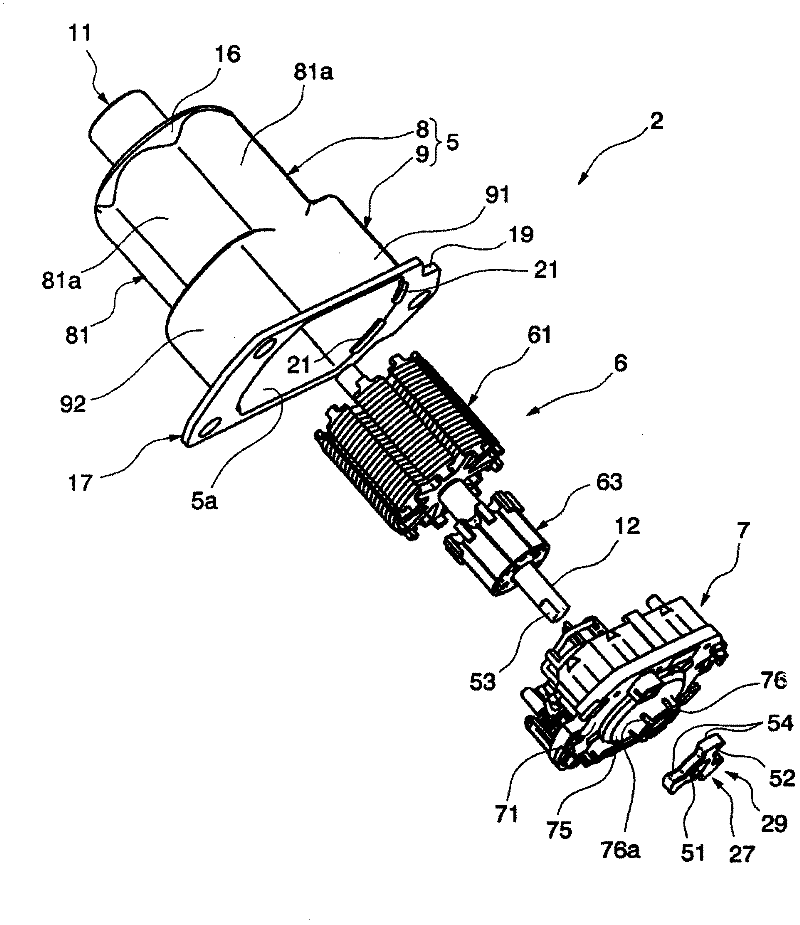
[0070] figure 1 It is a perspective view of the electric motor 1 with a speed reducer. figure 2 It is an exploded perspective view of the motor 1 with a speed reducer. Figure 3A and Figure 3B Indicates electric motor 2, Figure 3A is an exploded perspective view, Figure 3B yes Figure 3A An enlarged view of the armature 6 in .
[0071] Such as Figure 1 ~ Figure 3B As shown, an electric motor 1 with a speed reducer is used, for example, as a driving source of a power window device of a vehicle, and it includes an electric motor 2 and a worm reduction mechanism 3 connected to the rotating shaft 12 of the electric motor 2, and the electric motor 2 and the worm reduction mechanism 3 A connector unit 4 for supplying electric power to the electric motor 2 is provided between the mechanisms 3 .
[0072] (electric motor)
[0073] ...
no. 2 approach
[0181] Next, based on Figure 7 A second embodiment of the present invention will be described.
[0182] Figure 7 It is a longitudinal sectional view of the motor case 5 of the second embodiment. In addition, the same code|symbol is attached|subjected and demonstrated about the same form as 1st Embodiment, but the description is abbreviate|omitted (it is also the same in the following embodiment).
[0183] In this second embodiment, the following basic structure is the same as that of the above-mentioned first embodiment (it is also the same in the following embodiments): the electric motor 1 with a speed reducer is used, for example, as a drive source of a power window device of a vehicle, and Comprising an electric motor 2 and a worm reduction mechanism 3 connected to the rotating shaft 12 of the electric motor 2, a connector unit 4 for supplying electric power to the electric motor 2 is provided between the electric motor 2 and the worm reduction mechanism 3; the electri...
no. 3 approach
[0188] Next, based on Figure 8A and Figure 8B A third embodiment of the present invention will be described.
[0189] Figure 8A and Figure 8B Showing the motor casing 205 of the third embodiment, Figure 8A is the side view, Figure 8B is along Figure 8A Sectional view of the B-B line.
[0190] Here, if Figure 8A , Figure 8B As shown, the difference between the first embodiment and the third embodiment is that the yoke 8 of the first embodiment shown is formed in a substantially hexagonal shape when viewed from above in the axial direction, while the yoke 208 of the third embodiment is formed as It is roughly dodecagonal in plan view along the axial direction.
[0191] The motor housing 205 is a member formed by drawing a metal plate by pressing or the like, and is composed of a bottomed cylindrical yoke portion 208 and an oblong brush holder housing portion 9, wherein the brush holder housing portion 9 It is formed integrally with the end of the opening 208 a...
PUM
 Abstract
Description
Claims
Application Information
 - R&D
- Intellectual Property
- Life Sciences
- Materials
- Tech Scout
- Unparalleled Data Quality
- Higher Quality Content
- 60% Fewer Hallucinations
Browse by: Latest US Patents, China's latest patents, Technical Efficacy Thesaurus, Application Domain, Technology Topic, Popular Technical Reports.
© 2025 PatSnap. All rights reserved.Legal|Privacy policy|Modern Slavery Act Transparency Statement|Sitemap|About US| Contact US: help@patsnap.com


