Bolt-lock module

A latching and elastic arm technology, which is applied in the field of latching modules of electronic devices, can solve the problems of insufficient interference, low structural strength, falling off of the casing, etc.

Inactive Publication Date: 2012-04-04
INVENTEC CORP
View PDF0 Cites 0 Cited by
  • Summary
  • Abstract
  • Description
  • Claims
  • Application Information

AI Technical Summary

Problems solved by technology

[0003] Since the pusher is usually placed on the transmission part by means of a pair of elastic hooks, it is not easy to be stuck in the transmission part during the assembly process either because of its excessive structural strength, or because of its low structural strength or the gap with the transmission part. The amount of interference between them is insufficient, and it is easy to fall off from the casing due to vibration or foreign objects.

Method used


Image

  • Bolt-lock module
  • Bolt-lock module
  • Bolt-lock module

Examples


Embodiment Construction

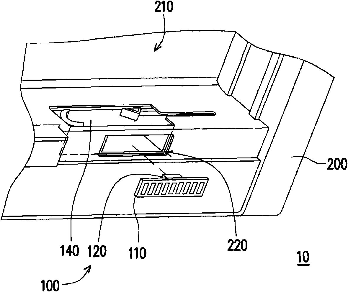
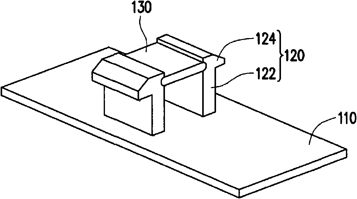
[0034] figure 1 It is an assembly diagram of a latch module according to an embodiment of the present invention. figure 2 yes figure 1 A schematic diagram of the pusher and buckle in another perspective. Please also refer to figure 1 up figure 2 , in this embodiment, the electronic device 10 is, for example, a notebook computer, which includes a latch module 100 and a casing 200, wherein the latch module 100 is assembled on the casing 200, and is used to provide the electronic device 10 for installation or It is used for removing a rechargeable battery (not shown).

[0035] In this embodiment, the casing 200 has an accommodating space 210 for accommodating the above-mentioned rechargeable battery. The latch module 100 includes a pusher 110 , a buckle 120 , a limiter 130 and a transmission member 140 , wherein the transmission member 140 is disposed inside the casing 200 , and the pusher 110 is slidably disposed outside the casing 200 A groove 220 is formed, and the buc...


PUM


Abstract

A bolt-lock module is suitable for being assembled on a casing of an electronic device. The bolt-lock module comprises a moving piece, a clamping piece and limit pieces. The moving piece can be assembled in a groove of the casing in slidable mode, and the clamping piece is assembled on the moving piece and comprises a plurality of elastic arms. Each elastic arm is provided with a first end and a second end. The first ends are connected with the moving piece, and the second ends extend towards the casing and penetrate through the casing. Each elastic arm is provided with a limit portion, and the limit pieces are clamped in the limit portions in detachable mode so as to limit deformation of the elastic arms relative to the moving piece.

Description

technical field [0001] The present invention relates to a latch module, and in particular to a latch module applied to electronic devices. Background technique [0002] Generally, the battery used in the power supply of a common notebook computer or a mobile phone is usually combined with a device on the back side of the computer casing, and the battery is disassembled by a bolt lock. The structure of the latch module is usually provided with a push piece on the back of the casing, and the push piece passes through the casing and is clamped on a transmission piece on the inner surface of the casing, so that the user can drive the transmission by pushing the push piece. The parts push the battery top out of the accommodating groove of the casing, so as to achieve the purpose of opening and closing the battery. [0003] Since the pusher is usually placed on the transmission part by means of a pair of elastic hooks, it is not easy to be stuck in the transmission part during as...

Claims


Application Information

Patent Timeline
IPC IPC(8): H05K5/02H05K7/12H01M2/10
CPCY02E60/12Y02E60/10
Inventor 施彦玮
Owner INVENTEC CORP
Why Eureka
Try Eureka