
Uplink resource allocation method and uplink resource allocation device

A resource allocation and resource block technology, applied in the field of uplink resource allocation methods and uplink resource allocation devices, can solve the problems of reducing the number of users that the system can accommodate, waste of allocated resources, and low utilization of system resources, so as to increase the capacity of the system. The number of users accommodated, the effect of reducing waste of resources and improving the utilization of system resources

Active Publication Date: 2012-04-04
POTEVIO INFORMATION TECH
View PDF4 Cites 10 Cited by
  • Summary
  • Abstract
  • Description
  • Claims
  • Application Information

AI Technical Summary

Problems solved by technology

[0015] It can be seen from the above that the existing resource allocation methods of time-division allocation or code-division allocation are relatively single, which is likely to cause waste of resource allocation and cannot flexibly match and adapt to service resource requirements. For example, for time-division allocation methods, due to The base station allocates all the code channel resources in the calculated time slot to the user. For the user transmitting the SPS service, the user may only need some code channel resources in the time slot to meet the SPS service requirements (user The amount of cache), like this, just wasted other code channel resources in this time slot, thereby also limited the maximum number of SPS users that the TD-SCDMA system can accommodate; Although the code division allocation method has a smaller Resource allocation granularity, but similar problems exist
That is to say, the existing uplink resource allocation method, due to the single resource allocation method, leads to the waste of allocated resources, reduces the number of users that the system can accommodate, makes the system resource utilization rate low, and cannot match and adapt to multi-service resources. requirements, especially for the uplink resource allocation of small data volume services

Method used


Image

  • Uplink resource allocation method and uplink resource allocation device
  • Uplink resource allocation method and uplink resource allocation device
  • Uplink resource allocation method and uplink resource allocation device

Examples


Embodiment Construction

[0083] In order to make the purpose, technical solution and advantages of the present invention clearer, the present invention will be further described in detail below in conjunction with the accompanying drawings and specific embodiments.

[0084] In the prior art, uplink resource allocation adopts time-division allocation or code-division allocation. Since the granularity of resource allocation is single, the allocated resources are likely to be larger than the user's buffer capacity, resulting in waste of resources. In the embodiment of the present invention, time-division The resource allocation method combining allocation and code division allocation, comprehensively consider the time slot resource and the code channel resource of the time slot, refer to the configuration information transmitted by the RNC through NBAP signaling and the scheduling information reported by the user, and calculate the actual buffer size of the user. The number of required time slots and the ...


PUM


Abstract

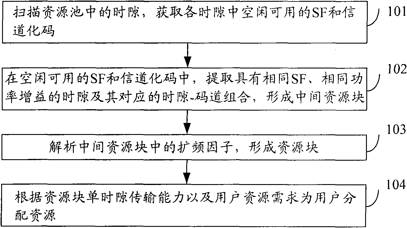
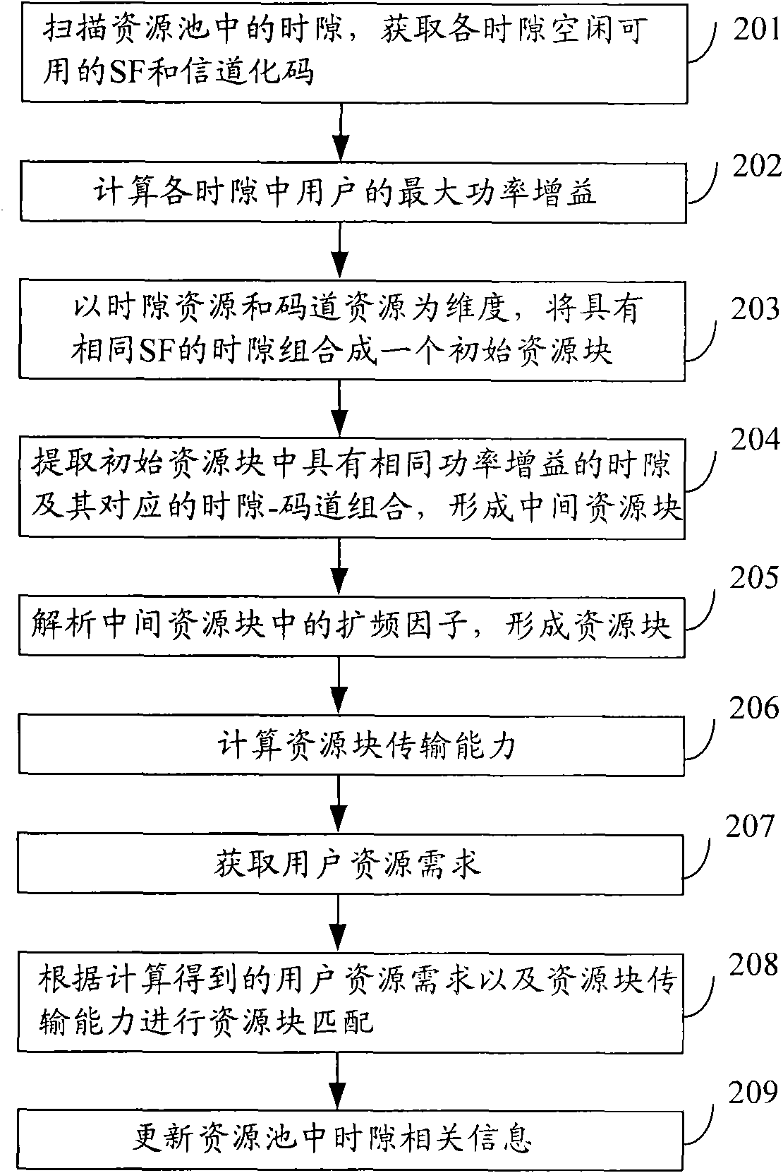
The invention discloses an uplink resource allocation method, which includes scanning time slots in a resource pool to obtain free available spreading factors SF and channelization codes in all the time slots, extracting time slots with identical SF and identical power gains and corresponding time slot-code channel combinations in the free available SF and the channelization codes to form a middle resource block, analyzing spreading factors in the middle resource block to form a resource block, and allocating resources for users according to transmission capacity of a single time slot of the resource block and user resource requirements. An uplink resource allocation device is further disclosed. By means of the uplink resource allocation method and the uplink resource allocation device, resource waste in allocation can be reduced, the number of users a system can accommodate is increased, and resource use ratio of the system is improved.

Description

technical field [0001] The present invention relates to mobile communication resource allocation technology, in particular to an uplink resource allocation method and an uplink resource allocation device. Background technique [0002] As a further evolution of the Time Division-Synchronous Code Division Multiple Access (TD-SCDMA, Time Division-Synchronous Code Division Multiple Access) system, the Third Generation Partnership Project (3GPP, 3 rd Generation Partnership Project) introduces Time Division Duplex (TDD, Time Division Duplex) High Speed ​​Packet Access Plus (HSPA+, High Speed ​​Package Access Plus) technology in R8. From the evolution of High Speed ​​Uplink Packet Access (HSUPA, High Speed ​​Uplink Packet Access) of TD-SCDMA system to HSPA+, the scheduling algorithm, as the core algorithm of system wireless resource management and resource allocation, has always been the focus of research. The base station reasonably allocates cell resources and user transmission...

Claims


Application Information

Patent Timeline
IPC IPC(8): H04W52/30H04W72/04
Inventor 杨茜朱颖
Owner POTEVIO INFORMATION TECH
Learn More