
Loading and unloading system

A technology for articles and conveyors, which is applied in the field of speed improvement, and can solve problems such as inability to follow, reduction in supply and export speed, etc.

Active Publication Date: 2012-04-04
MURATA MASCH LTD
View PDF4 Cites 10 Cited by
  • Summary
  • Abstract
  • Description
  • Claims
  • Application Information

AI Technical Summary

Problems solved by technology

However, with the increase in the size of the substrate, the supply and unloading speed decreases, and it may not be able to follow the processing on the processing equipment side.

Method used


Image

  • Loading and unloading system
  • Loading and unloading system
  • Loading and unloading system

Examples


Embodiment Construction

[0023] Hereinafter, the best embodiment for carrying out the present invention will be described. The scope of the present invention should be determined based on the description of the patent claims, with reference to the description in the specification and known technologies in the field, and based on the understanding of those skilled in the art. Various changes can be made within the scope not departing from the spirit of the invention. In particular, a plurality of embodiments and modifications described in this specification can be combined arbitrarily as necessary.

[0024] (Example)

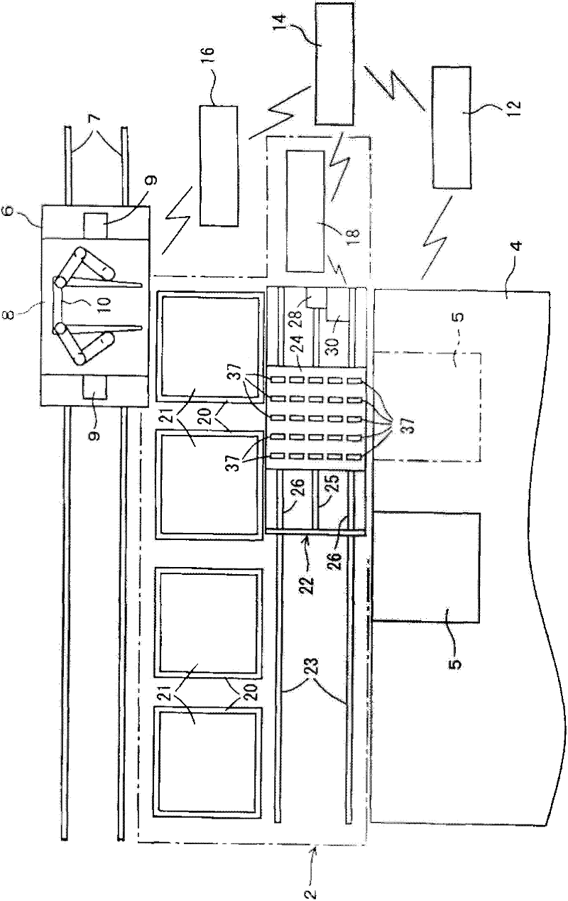
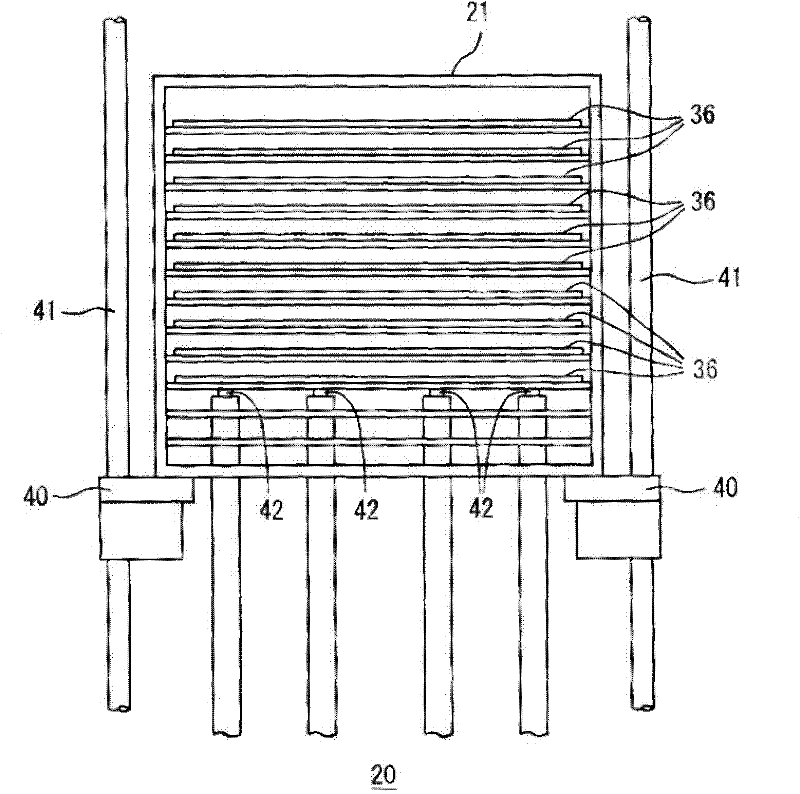
[0025] Figure 1 to Figure 7 Examples and modifications thereof are shown. In the figure, 2 is a supply and unloading system, between the station 5 of the processing apparatus 4 and the cassette station 20, supplies and unloads articles such as liquid crystal display substrates one article at a time. Furthermore, in addition to this, supply and discharge are also performed between the...


PUM


Abstract

A loading and unloading system can shorten the moving time of a moving trolley and increase the material supply conveying frequency. The system is configured in a way to make multiple articles contained inside a box supplied to a processing device one by one. Multiple box carrying platforms arranged in a line are applied for carrying boxes. Movable trolleys are moving along a linear path between the box carrying platforms and a station for processing devices. A sliding conveyor equipped on the movable trolley and capable of free motion is made to move simultaneously with the movable trolley through a controller.

Description

technical field [0001] The present invention relates to a supply and carry-out system, and more particularly to an improvement in the speed of supply and carry-out of articles. Background technique [0002] A system is known that supplies and unloads articles such as liquid crystal display substrates, plasma panel display substrates, and solar cell substrates one at a time to a processing device (Patent Document 1: JP2004-168483A). In Patent Document 1, a trolley equipped with a transfer device such as an articulated arm (SCARA arm) is disposed between the cassette and the station of the processing device, and the trolley is driven between the cassette and the station to pass through the transfer device. Move items. However, as the size of the substrate increases, the supply and unloading speed decreases, and it may not be possible to follow the processing on the processing apparatus side. Therefore, the inventors of the present invention conducted research on a technology...

Claims


Application Information

Patent Timeline
IPC IPC(8): B65G49/06
CPCB65G49/061B65G49/063G02F1/1303H01L21/67706H01L21/67769
Inventor 分部健二
Owner MURATA MASCH LTD
Learn More